Electricity, Magnetism & Circuits — Chapter Practice, Grade 12
Relate charge, fields, voltage, circuits, induction, stored energy, and electrical power.
Problem 1
- attractive
- repulsive
- zero
- always gravitational
Answer and explanation
repulsive
Like charges repel, so two positive charges push apart.
Problem 2
Answer and explanation
50000 N/C
E = F ÷ q = 0.1 ÷ (2 × 10⁻⁶) = 50,000 N/C.
Problem 3
Answer and explanation
0.6 N
F = kq₁q₂/r² = (9 × 10⁹)(2 × 10⁻⁶)(3 × 10⁻⁶) ÷ (0.3)² = 0.054 ÷ 0.09 = 0.6 N.
Problem 4
- glass
- copper
- dry wood
- rubber
Answer and explanation
copper
Copper is a metal with free-moving electrons, making it an excellent conductor — which is why wires are made of it.
Problem 5
Answer and explanation
0.9 N
F = kq₁q₂/r² = (9 × 10⁹)(3 × 10⁻⁶)(3 × 10⁻⁶) ÷ (0.3)² = 0.081 ÷ 0.09 = 0.9 N.
Problem 6
Answer and explanation
In a conductor, such as copper, some electrons are free to move through the material, so charge flows easily. In an insulator, such as rubber or glass, the electrons are held tightly to their atoms and cannot move freely, so charge does not flow. That is why wires use a copper conductor coated in a rubber insulator.
Problem 7
Hints
Distance is center-to-center under the point-charge model.
Answer and explanation
Away from the other charge: like charges repel, with equal and opposite interaction forces.
Problem 8
Hints
State what the supplied observations or conditions establish, and separate that from any assumption.
Answer and explanation
F=qE=6.0×10⁻⁴ N along the field for this positive charge.
Problem 9
Answer and explanation
Left, because the electron’s charge is negative and F=qE.
An electric field assigns force per positive test charge: E=F/q for a sufficiently small nonperturbing test. A positive source has outward field direction; a negative source has inward direction. A positive test charge feels force along E while a negative one feels force opposite E. Field units N/C differ from force units N. Field arrows are local direction indicators, not paths every released charge must follow.
Left, because the electron’s charge is negative and F=qE.
Response criteria
- Interpret labels, structures, axes, units and directions correctly.
- Explain the physical or environmental relationship or mechanism.
- Respect stated assumptions and distinguish observation from inference.
Problem 10
Answer and explanation
F=qE gives+0.0010 N east for+2 μC and−0.0015 N, i.e.west, for−3 μC. The field is unchanged in the ideal nonperturbing-test model.
F=qE gives+0.0010 N east for+2 μC and−0.0015 N, i.e.west, for−3 μC.
The field is unchanged in the ideal nonperturbing-test model.
Response criteria
- Use the stated measurements or conditions, with correct units.
- Connect the result to the physical or environmental mechanism or evidence relationship.
- Identify the assumption, model limit or further evidence requested.
Problem 11
Answer and explanation
4 A
I = Q ÷ t = 20 ÷ 5 = 4 A.
Problem 12
- volts
- ohms
- amperes
- joules
Answer and explanation
amperes
Current is the flow of charge per second, measured in amperes (amps).
Problem 13
Answer and explanation
12 V
V = W ÷ Q = 36 ÷ 3 = 12 V.
Problem 14
- a long, thin wire
- a long, thick wire
- a short, thin wire
- a short, thick wire
Answer and explanation
a short, thick wire
Resistance decreases with shorter length and greater thickness, so a short, thick wire resists the least.
Problem 15
Answer and explanation
20 C
Rearranging I = Q ÷ t gives Q = I × t = 2 × 10 = 20 C.
Problem 16
Answer and explanation
Voltage is like the water pressure from a pump that pushes the water along. Current is like the amount of water actually flowing past a point each second. Resistance is like a narrow section of pipe that restricts the flow. Higher pressure (voltage) drives more flow (current), while a tighter pipe (more resistance) reduces it.
Problem 17
Hints
Amperes are coulombs per second.
Answer and explanation
R=V/I=4 Ω.
Problem 18
Hints
State what the supplied observations or conditions establish, and separate that from any assumption.
Answer and explanation
No. Power P=VI also depends on voltage.
Problem 19
Answer and explanation
0.50 A under the same operating conditions.
Resistance relates voltage across a component to current through it; an ohmic model uses constant R so V=IR and the current–voltage graph is linear through the origin. Many real devices are nonohmic or change resistance as they heat. A curved graph does not violate energy conservation; it means a single constant-R approximation is inadequate. Read whether the vertical axis is current or voltage before interpreting the slope as R or 1/R.
0.50 A under the same operating conditions.
Response criteria
- Interpret labels, structures, axes, units and directions correctly.
- Explain the physical or environmental relationship or mechanism.
- Respect stated assumptions and distinguish observation from inference.
Problem 20
Answer and explanation
I=9/12=0.75 A; P=VI=6.75 W; E=Pt=270 J. The stated constant resistance and voltage must persist over the interval.
I=9/12=0.75 A; P=VI=6.75 W; E=Pt=270 J.
The stated constant resistance and voltage must persist over the interval.
Response criteria
- Use the stated measurements or conditions, with correct units.
- Connect the result to the physical or environmental mechanism or evidence relationship.
- Identify the assumption, model limit or further evidence requested.
Problem 21
Answer and explanation
10 V
V = IR = 2 × 5 = 10 V.
Problem 22
Answer and explanation
8 Ω
R = V ÷ I = 24 ÷ 3 = 8 Ω.
Problem 23
Answer and explanation
20 Ω
In series, resistances add: 4 + 6 + 10 = 20 Ω.
Problem 24
- the same through all of them
- larger in the bigger resistors
- smaller in the bigger resistors
- zero
Answer and explanation
the same through all of them
A series circuit has one single path, so the identical current flows through every component.
Problem 25
Answer and explanation
6 Ω
1/R = 1/12 + 1/12 = 2/12 = 1/6, so R = 6 Ω. (For two equal resistors, the parallel total is always half of one.)
Problem 26
Answer and explanation
0.5 A
Rearranging P = IV gives I = P ÷ V = 60 ÷ 120 = 0.5 A.
Problem 27
Hints
Kirchhoff's loop balance provides a check.
Answer and explanation
R_eq=3 Ω; I_total=12/3=4 A, with 2 A per branch.
Problem 28
Hints
State what the supplied observations or conditions establish, and separate that from any assumption.
Answer and explanation
Each branch spans the same two electrical nodes, so it has the same potential difference.
Problem 29
Answer and explanation
Smaller for more than one finite positive branch in this ideal model.
An equivalent resistance gives the same voltage–total-current relation at a chosen pair of terminals as the ideal resistor network. Series resistances add; parallel conductances 1/R add. A 2 Ω equivalent for 6 Ω parallel with 3 Ω is smaller than either branch resistance because it offers more conducting paths. This does not mean either actual resistor changed its own resistance or that branch currents equal the total current.
Smaller for more than one finite positive branch in this ideal model.
Response criteria
- Interpret labels, structures, axes, units and directions correctly.
- Explain the physical or environmental relationship or mechanism.
- Respect stated assumptions and distinguish observation from inference.
Problem 30
Answer and explanation
Currents are 3 A and 1 A; total 4 A. Req=12/4=3 Ω and P=12×4=48 W. Branch powers 36 W and 12 W sum consistently.
Currents are 3 A and 1 A; total 4 A.
Req=12/4=3 Ω and P=12×4=48 W.
Branch powers 36 W and 12 W sum consistently.
Response criteria
- Use the stated measurements or conditions, with correct units.
- Connect the result to the physical or environmental mechanism or evidence relationship.
- Identify the assumption, model limit or further evidence requested.
Problem 31
- stick together
- repel each other
- lose their magnetism
- attract strongly
Answer and explanation
repel each other
Like magnetic poles repel, just as like charges do, so two north poles push apart.
Problem 32
- rubbing a balloon to charge it
- rubbing a magnet on a piece of iron
- passing an electric current through a coil of wire
- cooling a wire until it is very cold
Answer and explanation
passing an electric current through a coil of wire
A current flowing through a coil produces a magnetic field, forming an electromagnet that can be switched on and off.
Problem 33
- the wire is warm
- the coil is made of copper
- a magnet is held motionless inside it
- the magnetic field through it is changing
Answer and explanation
the magnetic field through it is changing
Electromagnetic induction requires a changing magnetic field; a stationary field induces no current.
Problem 34
Answer and explanation
0.4 N
F = BIL = 0.2 × 4 × 0.5 = 0.4 N. The BIL form applies because current and field are perpendicular; otherwise include sinθ.
Problem 35
- electrical energy into mechanical (motion) energy
- mechanical energy into electrical energy
- heat energy into light energy
- sound energy into motion
Answer and explanation
electrical energy into mechanical (motion) energy
A motor uses the force on a current-carrying coil in a magnetic field to turn electrical energy into rotational motion.
Problem 36
Answer and explanation
A generator spins a coil of wire inside a magnetic field (or spins a magnet near a coil). The constantly changing magnetic field through the coil induces a voltage by electromagnetic induction, driving a current. It is a motor in reverse because a motor takes in electricity to produce motion, while a generator takes in motion to produce electricity — the same parts, run the opposite way.
Problem 37
Hints
Zero force here does not mean no magnetic field.
Answer and explanation
F=2×3×0.5=3 N.
Problem 38
Hints
State what the supplied observations or conditions establish, and separate that from any assumption.
Answer and explanation
A changing flux produces an induced emf; current depends on the circuit being closed and its impedance.
Problem 39
Answer and explanation
Zero for a uniform field and flat loop, because θ=90° from the area normal.
Magnetic flux measures the field passing through an oriented surface. For a uniform field and flat area, ΦB=BAcosθ, where θ is between B and the area normal, not the surface itself. A loop can have nonzero field but zero net flux when its plane is parallel to B. Flux is measured in webers and differs from field strength in teslas. Changing field, loop area or orientation can change flux.
Zero for a uniform field and flat loop, because θ=90° from the area normal.
Response criteria
- Interpret labels, structures, axes, units and directions correctly.
- Explain the physical or environmental relationship or mechanism.
- Respect stated assumptions and distinguish observation from inference.
Problem 40
Answer and explanation
F=|q|vB=0.012 N. Parallel motion gives sin 0=0 and zero magnetic-force magnitude in this model; electric forces would need a separate account.
F=|q|vB=0.012 N.
Parallel motion gives sin 0=0 and zero magnetic-force magnitude in this model; electric forces would need a separate account.
Response criteria
- Use the stated measurements or conditions, with correct units.
- Connect the result to the physical or environmental mechanism or evidence relationship.
- Identify the assumption, model limit or further evidence requested.
Problem 41
Answer and explanation
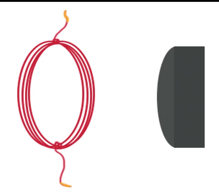
Force on the coil points toward the magnet; force on the magnet points toward the coil. They are equal/opposite and act on different bodies. Attraction was supplied as an assumption, not inferred from absent pole/current labels. An unchanged linked flux does not continuously induce emf; current also needs the appropriate conducting path and energy account.
Read source labels, scope, axes and intentional omissions.
Use the complete local explanation to draw a justified mechanism or calculate a supported quantity.
State what is observed, what is assumed and what evidence remains needed.
Response criteria
- Interpret the source labels, units and scope accurately.
- Explain the relevant mechanism with a labeled model or supported calculation.
- Identify a meaningful assumption, uncertainty or missing comparison.
Problem 42
Hints
Write the relationship first; substitute with consistent units.
Answer and explanation
12 J
qΔV=12.
Problem 43
Answer and explanation
Potential is scalar energy per charge; field is vector force per charge.
Response criteria
- State a scientifically accurate conclusion.
- Show the calculation or mechanism that supports it.
- Include units, conditions, or limits where relevant.
Problem 44
Hints
List the given quantities, select a relationship, and check units before substituting.
Answer and explanation
0.012 C
Q=CV=.012.
Problem 45
Answer and explanation
Voltage grows during charging; average charging voltage is half final voltage for a linear capacitor.
Response criteria
- State a scientifically accurate conclusion.
- Show the calculation or mechanism that supports it.
- Include units, conditions, or limits where relevant.
Problem 46
Hints
Potential is per charge; energy change also depends on q.
Answer and explanation
Q=CV=4.0×10⁻⁵ C on either plate in magnitude.
Problem 47
Hints
State what the supplied observations or conditions establish, and separate that from any assumption.
Answer and explanation
½×4.0×10⁻⁶×100=2.0×10⁻⁴ J.
Problem 48
Answer and explanation
Q=CV=240 μC, with equal opposite signs on the two ideal plates.
A capacitor stores energy through separated opposite charges. Its capacitance C=Q/V uses the magnitude Q on either plate and the plate-to-plate potential difference, under a linear model. The entire ideal two-plate device can have zero net charge while each plate is charged. Farads are coulombs per volt. Geometry and dielectric material affect capacitance; doubling Q at fixed C doubles V rather than necessarily changing C itself.
Q=CV=240 μC, with equal opposite signs on the two ideal plates.
Response criteria
- Interpret labels, structures, axes, units and directions correctly.
- Explain the physical or environmental relationship or mechanism.
- Respect stated assumptions and distinguish observation from inference.
Problem 49
Answer and explanation
Q=400 μC; U=½×50×10⁻⁶×64=0.0016 J=1.6 mJ. At16 V, U=6.4 mJ, four times as much. Actual ratings must be separately respected.
Q=400 μC; U=½×50×10⁻⁶×64=0.0016 J=1.6 mJ.
At16 V, U=6.4 mJ, four times as much.
Actual ratings must be separately respected.
Response criteria
- Use the stated measurements or conditions, with correct units.
- Connect the result to the physical or environmental mechanism or evidence relationship.
- Identify the assumption, model limit or further evidence requested.
Problem 50
Hints
Write the relationship first; substitute with consistent units.
Answer and explanation
1.8 W
P=VI.
Problem 51
Answer and explanation
Energy; it is power multiplied by time.
Response criteria
- State a scientifically accurate conclusion.
- Show the calculation or mechanism that supports it.
- Include units, conditions, or limits where relevant.
Problem 52
Hints
List the given quantities, select a relationship, and check units before substituting.
Answer and explanation
0.008 kWh
.004 kW×2h=.008 kWh.
Problem 53
Answer and explanation
Very low external resistance permits large current; internal resistance then dissipates substantial I²r heat.
Response criteria
- State a scientifically accurate conclusion.
- Show the calculation or mechanism that supports it.
- Include units, conditions, or limits where relevant.
Problem 54
Hints
Kilowatt-hour is energy, not power per hour.
Answer and explanation
1 kWh, equivalent to 3.6×10⁶ J.
Problem 55
Hints
State what the supplied observations or conditions establish, and separate that from any assumption.
Answer and explanation
The 10 W lamp uses less energy per equal operating time; broader impact also requires lifetime and other factors.
Problem 56
Answer and explanation
3 A and 36 W at unchanged 12 V, assuming the source maintains that voltage.
For ideal parallel loads sharing 12 V, source current is the sum of branch currents. Here 2+3+1=6 A and source output power is 72 W. A real source and conductors have operating limits and losses, so an ideal current sum is only part of a design comparison. Consider voltage regulation, continuous versus peak demand and the stated component ratings. Use supplied-data design here rather than modifying household wiring.
3 A and 36 W at unchanged 12 V, assuming the source maintains that voltage.
Response criteria
- Interpret labels, structures, axes, units and directions correctly.
- Explain the physical or environmental relationship or mechanism.
- Respect stated assumptions and distinguish observation from inference.
Problem 57
Answer and explanation
Saving=(0.015−0.009)×2500=15 kWh=5.40×10⁷ J/year. Production, transport, replacement lifespan or disposal is outside this operational-only result.
Saving=(0.015−0.009)×2500=15 kWh=5.40×10⁷ J/year.
Production, transport, replacement lifespan or disposal is outside this operational-only result.
Response criteria
- Use the stated measurements or conditions, with correct units.
- Connect the result to the physical or environmental mechanism or evidence relationship.
- Identify the assumption, model limit or further evidence requested.