Waves, Sound & Optics — Print · Physics & Environmental Science, Grade 12
Connect wave patterns, sound, electromagnetic radiation, interference, and refraction.
Printable chapter lessons and review.
Wave Properties
Learning goals
- I can distinguish transverse from longitudinal waves and identify amplitude, wavelength, frequency, and period.
- I can relate frequency, wavelength, and speed using v = f λ, and predict the result of two waves interfering.
Readings for this unit
Before this unit
Period, frequency, and wave speed.
Use the detailed parent plan: two core 50–60-minute sessions per focused unit, with a third assigned for selected calculation/modeling topics. First study the core explanation and Parts 1–2 with their figures/checks; next study Parts 3–4, the whole-unit application, worked cases, varied practice and exit check. Attempt reasoning before opening guidance. Extend time when actual understanding requires it; investigations and chapter assessments have separate sessions.
Start with something to explain
Does a crest carry the same bit of rope all the way across?
Illustrative evidence case. A rope marker oscillates locally while a crest moves onward.
Notice and wonder
Record two observations using the stated quantities or relationships. Keep observations separate from possible causes. Write one question that a new measurement could help answer.
Does a crest carry the same bit of rope all the way across?
Your first model
Separate marker motion from pattern propagation and label each axis.
Build the language from the idea
- wave
- A disturbance that transfers energy through space or a medium without transferring matter.
- transverse wave
- A wave in which the particles (or fields) vibrate perpendicular to the direction the wave travels, like a wave on a rope or light.
- longitudinal wave
- A wave in which particles vibrate parallel to the direction the wave travels, forming compressions and rarefactions, like sound.
- amplitude
- The maximum displacement of a wave from its rest position; a wave's energy is proportional to the square of its amplitude.
- wavelength (λ)
- The distance between two consecutive matching points on a wave, such as crest to crest, measured in meters.
- frequency (f)
- The number of complete waves passing a point each second, measured in hertz (Hz); the period is its inverse, T = 1/f.
- interference
- The result of two or more waves overlapping, adding together to reinforce (constructive) or cancel (destructive).
A wave propagates a disturbance and can transfer energy through interactions. In simple small-amplitude models, medium particles oscillate locally rather than traveling the entire propagation distance. Real surface waves can involve particle drift and other fluid motion, so a floating marker does not universally remain at one exact location. Electromagnetic waves require no material medium. State the wave model before using a no-net-matter-transfer approximation.
Waves come in two fundamental shapes. In a transverse wave, the particles of the medium vibrate *perpendicular* to the direction the wave travels — think of snapping a rope up and down while the pulse races horizontally away from your hand. Light and all electromagnetic waves are transverse. In a longitudinal wave, the particles vibrate *parallel* to the wave's travel, bunching into compressions and spreading into rarefactions; sound is the classic example, and you can model it by pushing and pulling one end of a stretched spring. Recognizing which type you are dealing with tells you a great deal about how the wave will behave.
Every wave is described by a small set of measurable quantities. Amplitude is the maximum displacement from rest, and it is the property tied to energy — but the link is sharper than 'bigger means stronger.' A wave's energy is proportional to the *square* of its amplitude, so doubling the amplitude carries four times the energy. Wavelength (λ) is the distance between matching points, easiest to measure crest to crest. Frequency (f), in hertz, counts how many whole waves pass each second, and the period (T) is the time for a single wave to pass. Frequency and period are reciprocals: if many waves pass each second, each must take very little time, so T = 1 ÷ f.
These quantities lock together in the single most useful relationship in the unit: wave speed equals frequency times wavelength, v = f × λ. The logic is direct — if many waves pass each second (high f) and each one is long (large λ), the wave front must be advancing quickly. Because the three quantities are linked, knowing any two always yields the third: f = v ÷ λ or λ = v ÷ f. A crucial subtlety for later units: the *speed* of a mechanical wave is set by the medium, not by the source. Shake a rope faster and you raise the frequency, but the pulse speed stays the same, so the wavelength shortens to compensate.
In a linear wave model, overlapping disturbances add signed displacements at each point. Matching phase can give constructive interference, while opposite phase can give local destructive interference. Zero combined displacement at a location does not mean energy is destroyed or absent throughout the system. Wave behavior outside a linear small-disturbance regime may not follow unchanged simple superposition. Keep the full pattern and model conditions in the account.
Master this handful of ideas and an enormous range of nature and technology opens up. The pitch of a note, the color of light, the channel your phone locks onto, and the destructive power of a storm swell all reduce to amplitude, wavelength, and frequency. Engineers who design antennas, concert halls, ultrasound scanners, and fiber-optic networks are, at bottom, controlling these same wave properties with precision — which is exactly why physicists insist on getting the vocabulary and the math of waves exactly right.
Model check: A wave transfers energy without requiring bulk material travel with the pattern. v=fλ=10 m/s andT=1/f=.20 s.
Build your understanding
Use the detailed parent plan: two core 50–60-minute sessions per focused unit, with a third assigned for selected calculation/modeling topics. First study the core explanation and Parts 1–2 with their figures/checks; next study Parts 3–4, the whole-unit application, worked cases, varied practice and exit check. Attempt reasoning before opening guidance. Extend time when actual understanding requires it; investigations and chapter assessments have separate sessions.
Part 1 · Separate propagation from local motion
A wave transports a disturbance and energy through space. In this transverse example, local material oscillates up and down while the pattern propagates horizontally. A material marker need not travel the entire distance with the crest. Sound in air is instead primarily longitudinal: local compression and expansion occur along propagation. Name which quantity oscillates and which direction the pattern travels before applying a rope picture to a different wave type.
Read the visual model
Identify the labeled structures and units, then trace the arrows or compare values under the caption’s stated conditions. Separate the displayed evidence from a further inference. Write your reasoning before opening the guidance.
Does the red up/down arrow mean energy propagates vertically in this drawing?
Visual reasoning — after your attempt
No. It indicates local transverse oscillation; the displayed wave propagates horizontally.
A wave carries a disturbance and transfers energy through a system. Local medium particles generally oscillate rather than traveling the entire wave distance. Transverse and longitudinal labels compare the direction of local oscillation with propagation; electromagnetic waves do not require a material medium.
A rope pulse travels along the rope while marked rope segments move mostly across that direction. A sound model uses local compression and expansion instead.
Pause and explain
Does a wave’s travel require each particle to travel with it?
Check your reasoning after answering
No. Interactions pass the disturbance along while local particles can oscillate about their positions.
Part 2 · Distinguish a spatial snapshot from a time record
Wavelength λ is the distance between equal-phase locations, such as adjacent crests, at one time. Period T is the interval between equal-phase events at one location, and frequency f=1/T counts cycles per second. A spatial curve and a time trace may look similar but their horizontal axes have different units. Never read a time period directly from a position axis or call a fixed-point oscillation trace a travel path.
Read the visual model
Identify the labeled structures and units, then trace the arrows or compare values under the caption’s stated conditions. Separate the displayed evidence from a further inference. Write your reasoning before opening the guidance.
What is frequency when the measured period is 0.004 s?
Visual reasoning — after your attempt
f=1/0.004=250 Hz; wavelength requires speed or a spatial record.
Wavelength is spatial separation between matching phase points, while period is the time for a repeating cycle at a location. A displacement-position graph and displacement-time graph can look alike but use different horizontal axes. Amplitude is measured from equilibrium, not crest to trough.
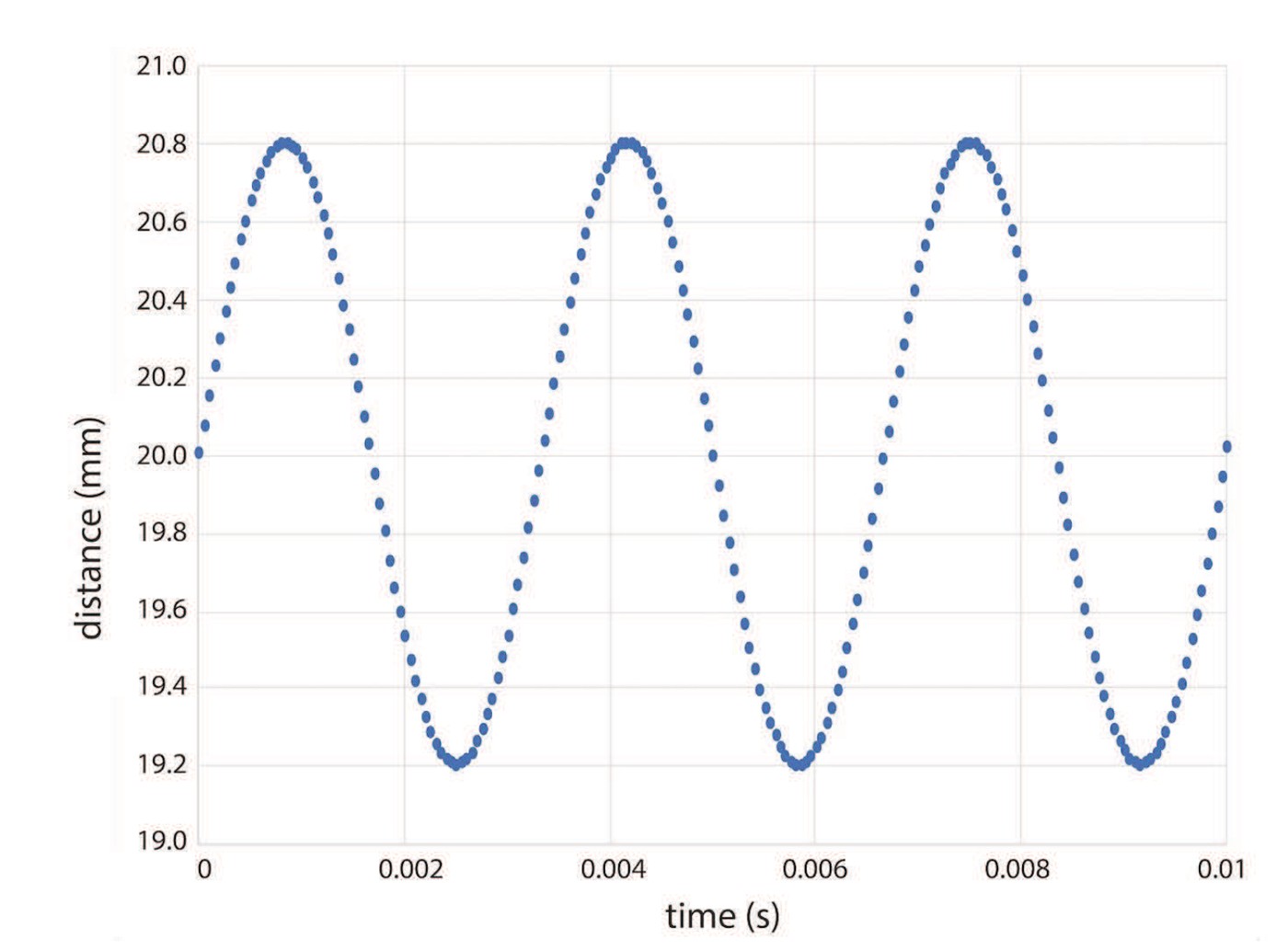
Two successive crests separated by 0.50 m identify wavelength. A marker returning to the same phase every 0.20 s identifies period.
Pause and explain
Why is crest-to-trough height twice amplitude for a symmetric wave?
Check your reasoning after answering
Amplitude is the maximum displacement from equilibrium; crest and trough lie on opposite sides, separated by two amplitudes.
Part 3 · Use the propagation relationship with conditions
Wave speed satisfies v=fλ for a steady periodic traveling wave. Frequency is cycles per second and wavelength is meters per cycle, so their product gives meters per second. In a nondispersive medium, changing source frequency changes wavelength while speed stays approximately fixed. In a dispersive medium, speed can depend on frequency, so “speed is always fixed” is too broad. Identify the medium, wave type and relevant approximation.
Read the visual model
Identify the labeled structures and units, then trace the arrows or compare values under the caption’s stated conditions. Separate the displayed evidence from a further inference. Write your reasoning before opening the guidance.
At speed 340 m/s, what wavelength corresponds to 680 Hz?
Visual reasoning — after your attempt
λ=v/f=0.50 m under the stated medium conditions.
For a periodic wave, v=fλ and f=1/T connect speed, frequency, wavelength, and period. Wave speed depends on the medium and conditions. When a source’s frequency remains fixed at a boundary, a speed change can change wavelength without changing frequency.
At fixed speed, increasing frequency reduces wavelength. At fixed frequency, a faster medium gives a longer wavelength. State which quantities are held fixed.
Pause and explain
Does a shorter wavelength always mean a faster wave?
Check your reasoning after answering
No. Speed depends on both frequency and wavelength; many comparisons change one while keeping the other or the medium fixed.
Part 4 · Distinguish amplitude from speed and frequency
Amplitude is the maximum departure from an equilibrium value for the chosen oscillating quantity. The two curves show different displacement amplitudes with the same wavelength. Within the same linear wave model, this change does not automatically alter frequency or propagation speed. Wave energy commonly depends on amplitude squared under specified conditions, but the proportionality depends on the medium and the quantity being plotted. Define the amplitude units before comparing waves.
Read the visual model
Identify the labeled structures and units, then trace the arrows or compare values under the caption’s stated conditions. Separate the displayed evidence from a further inference. Write your reasoning before opening the guidance.
Are the two curves enough to determine their numerical frequencies?
Visual reasoning — after your attempt
No. They show spatial shapes without a time record or numerical wave speed.
Amplitude can relate to carried energy in a specified wave model, but it is not the same as frequency or propagation speed. Simple linear wave models often treat speed as amplitude-independent over their range. Strong nonlinear disturbances can require a different model.
A more vigorous rope oscillation can increase amplitude without changing the source’s cycle rate. Compare one controlled variable at a time.
Pause and explain
What evidence tests an amplitude-independent speed claim?
Check your reasoning after answering
Measure travel time over the same distance for several amplitudes under the same medium conditions, and compare uncertainties.
Apply the whole unit · Connect a wave snapshot and timer record
Illustrative wave crests are 0.600 m apart and a fixed marker completes five cycles in 2.00 s. Assume uniform periodic propagation.
Your task
Find frequency, period, and wave speed. Predict wavelength in a second medium where speed is 2.00 m/s and source frequency remains unchanged, and explain the assumption.
What your response should show
- Define the system, quantities, units, and relevant conditions before selecting a model.
- Show intermediate calculations or a labeled evidence account, including signs or denominators.
- Explain how the supplied evidence supports the conclusion rather than reporting only an answer.
- Identify a meaningful uncertainty, model limit, or measurement needed to test the conclusion.
Response guidance — after your attempt
f=5/2.00=2.50 Hz; T=1/f=0.400 s.
v=fλ=2.50×0.600=1.50 m/s.
In the second medium λ=2.00/2.50=0.800 m.
The spatial and temporal measurements describe different features of the same periodic model. The boundary prediction keeps the source frequency fixed; the wavelength adjusts to the propagation speed. Neither record provides amplitude or total wave energy, so those quantities cannot be recovered from v=fλ alone.
Scientific references and source-model foundations
- OpenStax — thin-lens image formation
- OpenSciEd 8.2 — sound-wave foundations
- OpenSciEd public middle-school figure license — CC BY 4.0
Parent / teacher teaching notes
Ask students to label whether the horizontal axis represents position or time before reading any graph. Use that distinction to diagnose wavelength-period confusion. Ask the learner to explain each symbol, axis, unit and arrow before calculating. Calculated examples, supplied illustrative records and actual historical observations are labeled separately. Selected public OpenSciEd middle-school source figures are foundation examples, not complete high-school editions or an endorsement; all advanced explanations are supplied locally.
An animated transverse wave showing crests, troughs, amplitude, and wavelength.
The key idea
Waves propagate disturbances and energy; material can oscillate locally. Define spatial wavelength, time period and amplitude separately and state the model for v=fλ.
Wave Speed
v = f × λ
f is frequency in hertz (Hz); λ is wavelength in meters (m); v is wave speed in m/s. Rearranges to f = v ÷ λ or λ = v ÷ f.
Period and Frequency
T = 1 ÷ f
T is the period in seconds; f is frequency in Hz. Equivalently f = 1 ÷ T.
Worked examples
Example 1
- Use the wave speed equation v = f × λ.
- v = 25 × 8.
- = 200.
Example 2 · Worked application
- λ=v/f=100/25=4 m.
- T=1/f=1/25=0.040 s.
- Frequency and period are reciprocals.
Check v=fλ independently.
Example 3
- By superposition, the displacements add. In-phase waves interfere constructively.
- Add the amplitudes: 4 + 4.
- = 8.
Example 4 · Find and fix the mistake
- Test the claim against the stated conditions: Check v=fλ independently.
- Speed is set by the medium and wave type under that model; higher f then means shorter λ.
Check v=fλ independently.
Example 5 · Reason from the visual model
- Wave speed satisfies v=fλ for a steady periodic traveling wave. Frequency is cycles per second and wavelength is meters per cycle, so their product gives meters per second. In a nondispersive medium, changing source frequency changes wavelength while speed stays approximately fixed. In a dispersive medium, speed can depend on frequency, so “speed is always fixed” is too broad. Identify the medium, wave type and relevant approximation.
- λ=v/f=0.50 m under the stated medium conditions.
Calculated compatible wave quantities; the two table rows assume the same nondispersive speed.
Avoid these mistakes
- A wave transfers energy without requiring bulk material travel with the pattern.
Check your understanding
f=5 Hz,λ=2 m. Find speed and period.
Discuss the answer
v=fλ=10 m/s andT=1/f=.20 s.
Return to the phenomenon
Return to the initial case. Does a crest carry the same bit of rope all the way across? Revise your drawing or explanation using two named ideas and one stated limitation.
Compare explanations after your attempt
Energy propagates while material oscillates locally; wavelength, period and amplitude describe different features.
What should we investigate next?
Which comparison would test a remaining uncertainty? State what you would change, keep comparable and measure.
Investigate, calculate and revise
Keep a first model and an evidence-supported revision. Attempt each task before opening guidance; all required explanations and supplied-data routes are available locally.
Activity 1 · Return to the opening case
Use the opening phenomenon, unit definitions and explained Parts 1–4.
Your task
Return to the initial case. Does a crest carry the same bit of rope all the way across? Revise your drawing or explanation using two named ideas and one stated limitation.
Success criteria
- Use the stated observations and appropriate units.
- Connect a labeled model with the physical/environmental mechanism.
- State assumptions and an evidence limitation.
- Explain a substantive revision or next test.
Hint
Keep object/material identity, material transfer and energy account distinct.
Response guidance — discuss after your attempt
Energy propagates while material oscillates locally; wavelength, period and amplitude describe different features.
Activity 2 · Transfer to a changed case
Cover the worked answer and use the explained models, relationships and notebook.
Your task
A wave has period 0.020 s and wavelength 0.80 m. Find frequency and speed. If frequency doubles in the same nondispersive medium, find the new wavelength.
Success criteria
- Use the stated measurements or conditions, with correct units.
- Connect the result to the physical or environmental mechanism or evidence relationship.
- Identify the assumption, model limit or further evidence requested.
Hint
Name known quantities and conditions, show intermediate steps and check conservation.
Response guidance — discuss after your attempt
f=50 Hz and v=40 m/s. At100 Hz with the same 40 m/s speed, λ=0.40 m.
Words to know
- wave
- A disturbance that transfers energy through space or a medium without transferring matter.
- transverse wave
- A wave in which the particles (or fields) vibrate perpendicular to the direction the wave travels, like a wave on a rope or light.
- longitudinal wave
- A wave in which particles vibrate parallel to the direction the wave travels, forming compressions and rarefactions, like sound.
- amplitude
- The maximum displacement of a wave from its rest position; a wave's energy is proportional to the square of its amplitude.
- wavelength (λ)
- The distance between two consecutive matching points on a wave, such as crest to crest, measured in meters.
- frequency (f)
- The number of complete waves passing a point each second, measured in hertz (Hz); the period is its inverse, T = 1/f.
- interference
- The result of two or more waves overlapping, adding together to reinforce (constructive) or cancel (destructive).
Energy goes as amplitude squared — why a tsunami is so devastating
The lesson says bigger amplitude means more energy, but the real relationship is sharper: a wave's energy is proportional to the square of its amplitude, not just its amplitude. Double the amplitude and you carry four times the energy; triple it and you carry nine times. This is the same doubling-becomes-quadrupling pattern you meet in kinetic energy (KE = ½mv²). It is exactly why a tsunami — whose amplitude can be many times that of a normal swell — arrives with wildly disproportionate destructive power, and why earthquake engineers care so much about the amplitude of ground shaking, not merely its frequency.
Superposition and the magic of noise-cancelling headphones
The principle of superposition says that when waves overlap, their displacements simply add, point by point — and then each wave passes through untouched. Noise-cancelling headphones turn this into a product: a tiny microphone samples the incoming rumble of an engine, a processor generates a wave that is its exact mirror image (a crest wherever the noise has a trough), and the two superpose to near-silence through destructive interference. The same physics gives some seats in an auditorium 'dead spots,' and it is how engineers cancel vibration in everything from car cabins to precision telescopes.
Transverse and longitudinal together: reading an earthquake
Earthquakes broadcast both kinds of wave at once, and seismologists exploit the difference to find the epicenter. Fast P waves (primary) are longitudinal, squeezing and stretching the rock like sound; slower S waves (secondary) are transverse, shaking the ground side to side — and, tellingly, S waves cannot travel through liquid, which is how we first learned Earth's outer core is molten. Because P waves outrun S waves, the time gap between their arrivals at a station reveals the distance to the quake; combine readings from three stations and you triangulate the exact location.
Standing waves: when a trapped wave becomes music
Trap a wave between two boundaries — the fixed ends of a guitar string, the ends of an organ pipe — and its reflections superpose to form a standing wave: a frozen pattern of motionless nodes and violently oscillating antinodes. Only certain wavelengths 'fit' the length exactly, so an instrument sounds a specific set of frequencies (a fundamental plus its harmonics) rather than a smear of noise. This is the bridge from pure wave physics into the next lesson on sound, resonance, and why every instrument has its own characteristic voice.
Huygens vs. Newton: three centuries arguing what a wave even is
In the 1670 s the Dutch physicist Christiaan Huygens argued that light travels as a wave, while Isaac Newton favored tiny particles, or 'corpuscles.' Newton's towering reputation kept the particle picture dominant for over a century — until Thomas Young's 1801 double-slit experiment produced interference fringes that only waves can make. The debate seemed settled for the wave, yet twentieth-century physics revealed a stranger truth still: light behaves as both wave and particle, a paradox you will meet head-on in the lesson on the electromagnetic spectrum.
In the real world
Noise-cancelling headphones sample incoming sound and generate a wave that is exactly out of phase with it, using destructive interference to silence the roar of a jet engine.
Exit check
f=5 Hz,λ=2 m. Find speed and period.
Check your explanation after answering
v=fλ=10 m/s andT=1/f=.20 s.
Explain your reasoning without notes. If a key idea is missing, revisit the lesson and try again.
Sound
Learning goals
- I can describe sound as a longitudinal wave and relate pitch to frequency and loudness to amplitude.
- I can explain and calculate the Doppler effect and describe resonance and standing waves.
Readings for this unit
Before this unit
Mechanical waves and longitudinal compression.
Use the detailed parent plan: two core 50–60-minute sessions per focused unit, with a third assigned for selected calculation/modeling topics. First study the core explanation and Parts 1–2 with their figures/checks; next study Parts 3–4, the whole-unit application, worked cases, varied practice and exit check. Attempt reasoning before opening guidance. Extend time when actual understanding requires it; investigations and chapter assessments have separate sessions.
Start with something to explain
Why can a louder tone have the same pitch?
Illustrative evidence case. A vibrating source changes amplitude while its measured cycle interval stays fixed.
Notice and wonder
Record two observations using the stated quantities or relationships. Keep observations separate from possible causes. Write one question that a new measurement could help answer.
Why can a louder tone have the same pitch?
Your first model
Read its time axis and equilibrium position before comparing amplitudes.
Build the language from the idea
- longitudinal wave
- A wave in which particles vibrate back and forth in the same direction the wave travels, creating compressions and rarefactions.
- pitch
- How high or low a sound is perceived; determined by the sound wave's frequency.
- loudness
- How intense a sound seems; determined by the wave's amplitude and measured on the logarithmic decibel (dB) scale.
- medium
- The matter — solid, liquid, or gas — that a mechanical wave such as sound must travel through.
- Doppler effect
- The change in observed frequency (pitch) when a wave source and observer move relative to each other.
- resonance
- The large-amplitude vibration that occurs when a system is driven at its natural frequency.
- standing wave
- A stationary wave pattern of fixed nodes and antinodes formed when a wave reflects and interferes with itself, as on a guitar string.
Sound is a longitudinal wave, and that single fact explains most of its behavior. Instead of the up-and-down motion of a rope, the particles carrying a sound wave vibrate back and forth along the same line the wave travels, squeezing into compressions where they crowd together and stretching into rarefactions where they thin out. A struck tuning fork, a vibrating speaker cone, or your own vocal cords launches this pattern of pressure ripples outward. Because sound is nothing more than particles jostling their neighbors, it absolutely requires a medium — which is why space is silent, and why the booming explosions in science-fiction films could never actually reach your ears across a vacuum.
Sound speed depends on the medium’s elastic properties, density, and conditions such as temperature. For small disturbances in a suitable approximately nondispersive model, it is not set by source loudness or pitch. Room-temperature air is often approximated near 343 m/s; use the value stated for a particular task. Many solids transmit sound faster than air, but closely spaced particles alone are not a sufficient explanation, and material properties must be considered.
Pitch is perception strongly related to frequency for simple tones. Intensity is sound power per area, while perceived loudness also depends on frequency, duration and listener. A sound-intensity level uses decibels: β=10log₁₀(I/I₀), with a stated reference. A 10 dB difference means tenfold intensity, not tenfold perceived loudness. A pressure-amplitude ratio uses a different logarithmic factor under matched impedance conditions. Keep the physical and perceptual quantities distinct.
The Doppler effect compares emitted and received frequency. For a stationary receiver in still air and a subsonic source moving directly toward it, fobs=fsource v/(v−vs); recession uses v+vs. Source and receiver velocities are relative to the medium and the formula depends on geometry. Vacuum-light shifts use relativistic relations rather than simply substituting c into a sound formula; cosmic expansion adds another interpretive framework.
Standing-wave patterns can arise through suitable overlapping incident and reflected waves. Nodes have zero displacement amplitude and antinodes larger amplitude in the ideal pattern. Boundaries determine allowed modes. Driving near a natural frequency can produce resonance, while damping and coupling limit real amplitudes. A string and an air column have different displacement and pressure boundary conditions, so their harmonic patterns should not be transferred without checking those conditions.
Musical instruments combine source vibration, boundary-supported modes and energy loss. Walls transmit, reflect and absorb sound according to material, thickness, openings and frequency; a single “poor medium” label is insufficient. Sonar and biological echolocation use sound travel, while radar uses electromagnetic waves. Medical ultrasound uses acoustic interactions with tissues under controlled professional equipment and protocols; this course uses diagrams and supplied records rather than requiring exposure experiments.
Model check: Sound requires a medium; pitch and loudness measure different aspects. Round-trip 170 m; one-way distance 85 m.
Build your understanding
Use the detailed parent plan: two core 50–60-minute sessions per focused unit, with a third assigned for selected calculation/modeling topics. First study the core explanation and Parts 1–2 with their figures/checks; next study Parts 3–4, the whole-unit application, worked cases, varied practice and exit check. Attempt reasoning before opening guidance. Extend time when actual understanding requires it; investigations and chapter assessments have separate sessions.
Part 1 · Use the medium to explain sound propagation
Sound is a mechanical disturbance. In air it propagates mainly through longitudinal pressure and density variations: compressions are locally denser/higher-pressure regions and rarefactions are less dense regions. Molecules exchange forces with neighbors and oscillate locally rather than streaming from a speaker to your ear as a parcel. An ordinary vacuum cannot carry airborne sound because it lacks this material interaction chain.
Read the visual model
Identify the labeled structures and units, then trace the arrows or compare values under the caption’s stated conditions. Separate the displayed evidence from a further inference. Write your reasoning before opening the guidance.
What important limit separates sound from an electromagnetic wave?
Visual reasoning — after your attempt
Sound needs a material medium; electromagnetic waves can propagate through vacuum.
Ordinary sound is a mechanical disturbance requiring matter. In a simple fluid model, compressions and rarefactions propagate while particles oscillate locally. Speed depends on elastic properties, density, and conditions such as temperature; particle spacing alone is not a sufficient explanation.
A vacuum does not transmit ordinary sound. Many solids transmit it faster than air, but use the value supplied for the actual material rather than a universal ranking.
Pause and explain
Why is sound speed not determined by source loudness alone?
Check your reasoning after answering
The medium and its physical conditions govern the linear propagation model; louder excitation does not by itself specify a different speed.
Part 2 · Distinguish pitch, intensity, and loudness
Pitch is a perceptual attribute strongly related to frequency for simple tones. Intensity is acoustic power per area, while loudness is perception and depends on frequency, duration and listener. Timbre distinguishes sounds with different spectral or temporal structure even at similar pitch. Do not call a higher-amplitude trace “higher pitch” when its period is unchanged, and do not assume equal physical intensity always produces equal perceived loudness.
Read the visual model
Identify the labeled structures and units, then trace the arrows or compare values under the caption’s stated conditions. Separate the displayed evidence from a further inference. Write your reasoning before opening the guidance.
Can two tones have the same frequency but different intensity?
Visual reasoning — after your attempt
Yes. Their oscillation rates can match while amplitudes and power per area differ.
Frequency is strongly associated with perceived pitch, while intensity is physical power per area. Loudness also depends on frequency and listener response. Amplitude and intensity relationships need a stated model. A high-pitch sound need not be intense, and an intense sound need not be high-pitched.
For comparable waves in a linear medium, intensity is often proportional to amplitude squared. This does not make a loudness judgment a precise intensity measurement.
Pause and explain
Can frequency alone rank sound intensity?
Check your reasoning after answering
No. Frequency and intensity are different variables; source power, distance, and propagation also matter.
Part 3 · Interpret the decibel ratio
A sound-intensity level is β=10log₁₀(I/I₀) for a stated reference intensity I₀. Differences in decibels compare ratios: a 20 dB increase means 100 times the intensity, not 20 times. Decibels are not a direct linear loudness scale. The plotted points show selected calculated ratios on a linear horizontal axis; between-point connections are a guide rather than an exact smooth logarithmic curve.
Read the visual model
Identify the labeled structures and units, then trace the arrows or compare values under the caption’s stated conditions. Separate the displayed evidence from a further inference. Write your reasoning before opening the guidance.
What intensity ratio corresponds to a 30 dB increase?
Visual reasoning — after your attempt
10^(30/10)=1000, provided the levels use the same intensity reference.
Sound intensity level uses β=10 log₁₀(I/I₀) with a stated reference. A 10 dB difference corresponds to a tenfold intensity ratio, while 20 dB corresponds to a hundredfold ratio. Decibels are logarithmic; do not add intensity levels as if they were ordinary powers.
The same level difference does not establish an identical perceived-loudness change for every listener or frequency. Keep the physical ratio and perception distinct.
Pause and explain
What does a 3 dB increase approximately mean?
Check your reasoning after answering
It is about a factor of two in intensity because 10 log₁₀2≈3.01 dB; it is not simply three times the intensity.
Part 4 · Use travel-time and spreading models carefully
For an echo, a pulse travels to a reflector and back, so distance is vΔt/2 when the same sound speed applies both ways. For an ideal point source spreading uniformly without absorption, intensity falls as 1/r² because the same power crosses a growing spherical area. Real rooms have reflections, directional sources and absorption; the inverse-square comparison is not a universal rule for every microphone position indoors.
Read the visual model
Identify the labeled structures and units, then trace the arrows or compare values under the caption’s stated conditions. Separate the displayed evidence from a further inference. Write your reasoning before opening the guidance.
An echo returns after 0.40 s at 340 m/s. How far away is the reflector?
Visual reasoning — after your attempt
d=340×0.40/2=68 m in the stated still-air model.
An echo time covers a round trip when the signal returns to the source. For an ideal isotropic point source without reflections or absorption, intensity decreases as 1/r². Enclosed spaces and directional sources can differ. Specify the propagation path before applying either shortcut.
An echo returning after 0.50 s at 340 m/s corresponds to about 85 m one-way distance, not 170 m.
Pause and explain
When can doubling distance reduce intensity to one-quarter?
Check your reasoning after answering
Under the stated point-source geometric-spreading model with comparable conditions, without major absorption, reflections, or source-direction effects.
Apply the whole unit · Interpret an echo and intensity comparison
Illustrative echo returns after 0.400 s in air with sound speed 340 m/s. A separate ideal point-source record has intensity I at 2.00 m and no significant absorption or reflections.
Your task
Find reflector distance, predict intensity at 4.00 m, and calculate the intensity-level change. Explain why these are different measurements and why the spreading model may fail indoors.
What your response should show
- Define the system, quantities, units, and relevant conditions before selecting a model.
- Show intermediate calculations or a labeled evidence account, including signs or denominators.
- Explain how the supplied evidence supports the conclusion rather than reporting only an answer.
- Identify a meaningful uncertainty, model limit, or measurement needed to test the conclusion.
Response guidance — after your attempt
Round-trip distance=340×0.400=136 m; reflector distance=68.0 m.
At 4.00 m the intensity is I/4.
Level change=10 log₁₀(1/4)≈−6.02 dB.
The echo calculation needs the return-path assumption; the intensity calculation needs a source-geometry assumption. Neither is a hearing assessment. Walls, directionality, multiple reflected paths, and background sound can make indoor records differ from ideal inverse-square spreading.
Scientific references and source-model foundations
Parent / teacher teaching notes
Use supplied quiet observations or records. Ask why echo distance is halved and why decibels require an intensity ratio rather than a linear subtraction of powers. Ask the learner to explain each symbol, axis, unit and arrow before calculating. Calculated examples, supplied illustrative records and actual historical observations are labeled separately. Selected public OpenSciEd middle-school source figures are foundation examples, not complete high-school editions or an endorsement; all advanced explanations are supplied locally.
An animated longitudinal wave showing compressions and rarefactions moving through a line of particles.
The key idea
Sound needs a medium. Frequency strongly influences pitch, while intensity and loudness differ. Decibel ratios, Doppler shifts and standing waves require stated conditions.
Distance from Speed and Time
d = v × t
v is the speed of sound (about 343 m/s in air); t is time in seconds; d is distance in meters. For an echo, the sound covers 2d, so d = v × t ÷ 2.
Doppler Effect (moving source)
f′ = f × v ÷ (v ∓ vₛ)
f′ is the observed frequency; f is the source frequency; v is the speed of sound; vₛ is the source's speed. Use the minus sign when the source approaches, the plus sign when it recedes.
Fundamental Frequency (resonance)
f₁ = v ÷ (2L)
f₁ is the lowest resonant (fundamental) frequency of a string fixed at both ends or an open pipe of length L; v is the wave speed. Higher harmonics are whole-number multiples of f₁.
Worked examples
Example 1
- Rearrange v = f × λ to solve for wavelength: λ = v ÷ f.
- λ = 343 ÷ 686.
- = 0.5.
Example 2 · Worked application
- Beat frequency is the absolute frequency difference.
- 444−440=4 Hz.
- The amplitude envelope repeats about four times per second.
Beat frequency is distinct from the approximately 442 Hz pitch region.
Example 3
- The source is approaching, so use the minus sign: f′ = f × v ÷ (v − vₛ).
- f′ = 300 × 340 ÷ (340 − 40) = 300 × 340 ÷ 300.
- The 300 s cancel, leaving f′ = 340.
Example 4 · Find and fix the mistake
- Test the claim against the stated conditions: Beat frequency is distinct from the approximately 442 Hz pitch region.
- Loudness depends on amplitude and perception; frequency primarily influences pitch.
Beat frequency is distinct from the approximately 442 Hz pitch region.
Example 5 · Reason from the visual model
- A sound-intensity level is β=10log₁₀(I/I₀) for a stated reference intensity I₀. Differences in decibels compare ratios: a 20 dB increase means 100 times the intensity, not 20 times. Decibels are not a direct linear loudness scale. The plotted points show selected calculated ratios on a linear horizontal axis; between-point connections are a guide rather than an exact smooth logarithmic curve.
- 10^(30/10)=1000, provided the levels use the same intensity reference.
Calculated selected intensity-ratio points; not measured sound exposure or a safety threshold.
Avoid these mistakes
- Sound requires a medium; pitch and loudness measure different aspects.
Check your understanding
An echo returns after.50 s at 340 m/s. Find wall distance.
Discuss the answer
Round-trip 170 m; one-way distance 85 m.
Return to the phenomenon
Return to the initial case. Why can a louder tone have the same pitch? Revise your drawing or explanation using two named ideas and one stated limitation.
Compare explanations after your attempt
Amplitude/intensity and frequency describe different quantities; perceived loudness is not identical to either one alone.
What should we investigate next?
Which comparison would test a remaining uncertainty? State what you would change, keep comparable and measure.
Investigate, calculate and revise
Keep a first model and an evidence-supported revision. Attempt each task before opening guidance; all required explanations and supplied-data routes are available locally.
Activity 1 · Return to the opening case
Use the opening phenomenon, unit definitions and explained Parts 1–4.
Your task
Return to the initial case. Why can a louder tone have the same pitch? Revise your drawing or explanation using two named ideas and one stated limitation.
Success criteria
- Use the stated observations and appropriate units.
- Connect a labeled model with the physical/environmental mechanism.
- State assumptions and an evidence limitation.
- Explain a substantive revision or next test.
Hint
Keep object/material identity, material transfer and energy account distinct.
Response guidance — discuss after your attempt
Amplitude/intensity and frequency describe different quantities; perceived loudness is not identical to either one alone.
Activity 2 · Transfer to a changed case
Cover the worked answer and use the explained models, relationships and notebook.
Your task
Two sound intensity levels differ by 15 dB. Find their intensity ratio. A separate echo returns in 0.30 s at 340 m/s; find reflector distance.
Success criteria
- Use the stated measurements or conditions, with correct units.
- Connect the result to the physical or environmental mechanism or evidence relationship.
- Identify the assumption, model limit or further evidence requested.
Hint
Name known quantities and conditions, show intermediate steps and check conservation.
Response guidance — discuss after your attempt
The intensity ratio is 10^1.5≈31.6. Echo distance=340×0.30/2=51 m; the two calculations use different models and quantities.
Words to know
- longitudinal wave
- A wave in which particles vibrate back and forth in the same direction the wave travels, creating compressions and rarefactions.
- pitch
- How high or low a sound is perceived; determined by the sound wave's frequency.
- loudness
- How intense a sound seems; determined by the wave's amplitude and measured on the logarithmic decibel (dB) scale.
- medium
- The matter — solid, liquid, or gas — that a mechanical wave such as sound must travel through.
- Doppler effect
- The change in observed frequency (pitch) when a wave source and observer move relative to each other.
- resonance
- The large-amplitude vibration that occurs when a system is driven at its natural frequency.
- standing wave
- A stationary wave pattern of fixed nodes and antinodes formed when a wave reflects and interferes with itself, as on a guitar string.
Sound is faster in steel than air — and instant in neither
A common misconception is that sound is effectively instantaneous; in fact it travels at a definite, medium-dependent speed. In room-temperature air that is about 343 m/s, but in water roughly 1,480 m/s and in solid steel around 5,900 m/s — because tightly packed particles hand off the vibration far faster. That is why railroad workers in old films pressed an ear to the rail: the steel delivers the sound of an approaching train sooner and farther than the air. Temperature matters too — warmer air carries sound a little faster, since its molecules move more quickly.
Christian Doppler, Buys Ballot, and a trainful of trumpeters
In 1842 the Austrian physicist Christian Doppler predicted that a moving source should shift the pitch a listener hears. Three years later the Dutch scientist Buys Ballot staged one of science's most charming tests: he had trumpeters play a sustained note aboard an open railway car speeding past musicians with perfect pitch, who confirmed the note rose as the car approached and fell as it receded — exactly as Doppler foretold. The same effect, applied to light, later let astronomers discover that distant galaxies are rushing away, evidence for an expanding universe.
Decibels are logarithmic: why 'twice as loud' isn't twice the number
Loudness is measured on the decibel (dB) scale, and — like pH — it is logarithmic, not linear. Every 10 dB marks a tenfold jump in sound intensity, so a 60 dB conversation and a 110 dB rock concert differ by 50 dB, which is 10⁵ — about 100,000 times more intense, not 'roughly twice.' This is why loud sound damages hearing so much faster than people expect, and why safety limits on headphones and workplaces are written in decibels: a few extra dB hides a huge jump in the actual energy hitting your eardrum.
Resonance can shatter a glass — and rattle a bridge
Every object has natural frequencies at which it 'wants' to vibrate. Drive it at one and the amplitude builds enormously — resonance. A trained singer sustaining a note at a wine glass's natural frequency can feed it energy until it shatters; a child pumping a swing in rhythm climbs higher and higher on the same principle. Engineers respect resonance too: the 1940 collapse of the Tacoma Narrows Bridge, whose deck twisted itself apart in a moderate wind, is the textbook cautionary tale (its cause is better described as aeroelastic flutter, but it made resonance famous).
Echolocation and ultrasound: seeing with sound
Sound above 20,000 Hz — ultrasound — is inaudible to humans but immensely useful. Bats and dolphins echolocate, emitting rapid ultrasonic pulses and reading the returning echoes to map size, distance, and even the texture of prey in total darkness. We borrowed the trick: sonar lets ships and submarines 'see' the seafloor, and medical ultrasound images a developing fetus or a beating heart safely, using no radiation at all — just the timing and strength of reflected pressure waves, the very same physics that makes an echo bounce off a canyon wall.
In the real world
Doppler weather radar bounces microwaves off raindrops and reads the frequency shift of the return to measure how fast a storm's winds are moving toward or away from the station.
Exit check
An echo returns after.50 s at 340 m/s. Find wall distance.
Check your explanation after answering
Round-trip 170 m; one-way distance 85 m.
Explain your reasoning without notes. If a key idea is missing, revisit the lesson and try again.
Light & the Electromagnetic Spectrum
Learning goals
- I can describe light as an electromagnetic wave and order the spectrum by wavelength, frequency, and energy using c = f λ.
- I can explain wave-particle duality and calculate a photon's energy with E = h f.
Readings for this unit
Before this unit
Frequency, wavelength, and vacuum speed.
Use the detailed parent plan: two core 50–60-minute sessions per focused unit, with a third assigned for selected calculation/modeling topics. First study the core explanation and Parts 1–2 with their figures/checks; next study Parts 3–4, the whole-unit application, worked cases, varied practice and exit check. Attempt reasoning before opening guidance. Extend time when actual understanding requires it; investigations and chapter assessments have separate sessions.
Start with something to explain
Why can two equally bright-looking sources behave differently in a detector?
Illustrative evidence case. Sources have different spectra and the detector responds unevenly across wavelength.
Notice and wonder
Record two observations using the stated quantities or relationships. Keep observations separate from possible causes. Write one question that a new measurement could help answer.
Why can two equally bright-looking sources behave differently in a detector?
Your first model
Distinguish emitted energy, photon frequency and detector response.
Build the language from the idea
- electromagnetic (EM) wave
- A transverse wave of oscillating electric and magnetic fields that travels through a vacuum at the speed of light, c ≈ 3 × 10⁸ m/s.
- electromagnetic spectrum
- The full range of EM waves, ordered from long, low-energy radio waves to short, high-energy gamma rays.
- speed of light (c)
- The constant speed of all EM waves in a vacuum, about 3 × 10⁸ m/s — the universe's ultimate speed limit.
- photon
- A discrete packet, or quantum, of electromagnetic energy; the 'particle' of light, with energy E = h f.
- wave-particle duality
- The experimental fact that light (and matter) behaves as both a wave and a stream of particles, depending on how it is observed.
- Planck's constant (h)
- The fundamental constant linking a photon's energy to its frequency, h ≈ 6.63 × 10⁻³⁴ J·s.
Light is an electromagnetic wave — a self-sustaining ripple of oscillating electric and magnetic fields, each one regenerating the other as it propagates. James Clerk Maxwell showed in the 1860 s that these fields should travel together at a fixed speed, and that speed turned out to match the measured speed of light, revealing that light *is* an electromagnetic phenomenon. Crucially, an EM wave needs no medium at all; it sails through the vacuum of space at c ≈ 3 × 10⁸ m/s — fast enough to circle Earth roughly seven times in a single second, and the fastest anything can travel.
Visible light is only a sliver of a vast family. The electromagnetic spectrum arranges all EM waves by wavelength: from the longest, running through radio waves, microwaves, infrared, the narrow band of visible light our eyes detect, then ultraviolet, X-rays, and finally gamma rays with the shortest wavelengths. They are all fundamentally the same kind of wave, differing only in wavelength and frequency, and every one obeys the light-wave equation c = f × λ. Because c is fixed, wavelength and frequency trade off perfectly: a long-wavelength radio wave is low-frequency, while a short-wavelength gamma ray is extraordinarily high-frequency.
One clean pattern ties the whole spectrum together: as wavelength shortens, frequency and energy both climb. Radio waves carry very little energy; gamma rays carry enormous amounts. This is the difference between non-ionizing radiation (radio, microwave, infrared, visible), which lacks the energy to knock electrons loose, and ionizing radiation (much of ultraviolet, X-rays, gamma rays), which can break chemical bonds and damage DNA. It explains why radio waves stream harmlessly through your body all day while a dentist drapes you in lead before an X-ray, and why the visible band — safely mid-spectrum — is the light life evolved to see by.
For two centuries scientists argued whether light was a wave or a stream of particles, and the strange answer is both. Thomas Young's interference experiments proved light behaves as a wave; then in 1905 Albert Einstein explained the photoelectric effect — light ejecting electrons from a metal — by proposing that light also arrives in discrete packets called photons. A dim blue light can free electrons that an intense red light cannot, because what matters is the *energy per photon*, set by frequency, not the total brightness. Each photon's energy is E = h × f, where h is Planck's constant, 6.63 × 10⁻³⁴ J·s. This wave-particle duality is not a contradiction to resolve but a deep truth: which model you use depends on the situation.
Deciding *which* model to reach for is a genuine scientific skill. To predict how light spreads through a lens, bends around an obstacle, or produces interference fringes, the wave model is indispensable. To explain how a solar cell converts sunlight to current, how your eye's photoreceptors fire, or how a single high-energy gamma photon can shatter a molecule, the particle model is far more useful. Neither model is 'the truth' by itself; each is a tool that captures part of light's behavior, and a physicist learns to switch fluidly between them as the problem demands.
Because each band of the spectrum carries a different energy and interacts with matter differently, we have found a use for nearly all of it. We communicate through radio waves, cook with microwaves, feel warmth as infrared, and see by visible light; doctors image bones with X-rays and destroy tumors with gamma rays; astronomers build radio, infrared, and X-ray telescopes to reveal a universe invisible to the naked eye. Reading the electromagnetic spectrum is really a map of how energy travels across space and how it touches everything — from the warmth of the Sun to the signal reaching your phone right now.
Model check: Electromagnetic waves share vacuum speed but have different frequencies and photon energies. f=c/λ=1×10⁸ Hz. Use meters with SI c.
Build your understanding
Use the detailed parent plan: two core 50–60-minute sessions per focused unit, with a third assigned for selected calculation/modeling topics. First study the core explanation and Parts 1–2 with their figures/checks; next study Parts 3–4, the whole-unit application, worked cases, varied practice and exit check. Attempt reasoning before opening guidance. Extend time when actual understanding requires it; investigations and chapter assessments have separate sessions.
Part 1 · Distinguish vacuum speed and medium behavior
An electromagnetic wave is a coupled variation of electric and magnetic fields. It can propagate in vacuum at c, unlike a sound wave. In matter, interactions change phase speed and can produce wavelength-dependent refraction or absorption. The two curves symbolize field variation, not two bits of material moving up and down or a claim that field strengths have equal numerical units. State whether a speed refers to vacuum or a specified medium.
Read the visual model
Identify the labeled structures and units, then trace the arrows or compare values under the caption’s stated conditions. Separate the displayed evidence from a further inference. Write your reasoning before opening the guidance.
If visible light enters a medium with n=1.5, what phase speed follows v=c/n?
Visual reasoning — after your attempt
v≈2.00×10⁸ m/s in that stated medium model.
Electromagnetic radiation propagates in vacuum at c, about 3.00×10⁸ m/s. Frequency and wavelength differ across the spectrum while that vacuum speed is shared. Propagation in matter depends on the material and frequency; do not transfer the vacuum-speed claim to every medium.
A vacuum wavelength satisfies λ=c/f. In a transparent material, frequency is set by the source while speed and wavelength can change.
Pause and explain
Is violet light faster than red light in vacuum?
Check your reasoning after answering
No. They share c in vacuum; their frequencies and wavelengths differ.
Part 2 · Connect wave quantities with photon energy
A photon is a quantum of electromagnetic energy with E=hf. In vacuum f=c/λ, so shorter wavelength means larger energy per photon. Total beam energy also depends on photon number: one high-energy photon and many lower-energy photons are not the same interaction pattern. Frequency remains unchanged at a stationary boundary between media while wavelength changes with phase speed; use vacuum wavelength when applying hc/λ with c.
Read the visual model
Identify the labeled structures and units, then trace the arrows or compare values under the caption’s stated conditions. Separate the displayed evidence from a further inference. Write your reasoning before opening the guidance.
Does doubling intensity necessarily double the energy of each photon?
Visual reasoning — after your attempt
No. At fixed frequency it mainly increases photon arrival rate, not hf.
Photon energy is E=hf=hc/λ for vacuum wavelength. Higher frequency means higher energy per photon. Total beam energy also depends on photon number, intensity, and duration, so color alone cannot establish total delivered energy.
Two beams can have different photon energies but equal total energy because they contain different numbers of photons.
Pause and explain
Does a higher-energy photon imply a more powerful beam?
Check your reasoning after answering
Not necessarily. Beam power depends on energy delivered per time, including photon arrival rate.
Part 3 · Separate interactions across the spectrum
The electromagnetic spectrum orders radiation by frequency or vacuum wavelength. Radio, microwave, infrared, visible, ultraviolet, X-ray and gamma labels cover ranges, not separate fundamental wave species. A material may transmit, reflect or absorb different ranges depending on its structure. Ionization removes an electron and requires enough interaction energy under the relevant conditions; heating and photochemical changes can occur through other mechanisms. Explain an application using energy, material response and dose rather than a color label alone.
Read the visual model
Identify the labeled structures and units, then trace the arrows or compare values under the caption’s stated conditions. Separate the displayed evidence from a further inference. Write your reasoning before opening the guidance.
Why is “all radiation has the same biological effect” unsupported?
Visual reasoning — after your attempt
Photon energy, material interaction, absorbed amount and exposure conditions differ across situations.
Matter can absorb, reflect, transmit, or scatter radiation, depending on material and wavelength. Ionization requires sufficient energy for the relevant interaction; nonionizing radiation can still transfer energy. The spectrum is an organizing model, not a universal chart of harmless and harmful exposure.
A transparent material at visible wavelengths may absorb strongly in another band. A single visible appearance does not specify the full interaction spectrum.
Pause and explain
Can visible transparency prove infrared transparency?
Check your reasoning after answering
No. The response depends on wavelength and material; an infrared measurement or suitable material evidence is needed.
Part 4 · Use evidence for radiation applications
A detector converts a selected interaction into a measurable signal. Its spectral response is sensitivity as a function of wavelength or frequency, so a weak signal can mean weak radiation or poor detector sensitivity. Geometry, background and calibration also matter. Compare source-on/source-off records and an appropriate reference before making claims about transmission or energy. One visible observation cannot establish behavior across the entire electromagnetic spectrum.
Read the visual model
Identify the labeled structures and units, then trace the arrows or compare values under the caption’s stated conditions. Separate the displayed evidence from a further inference. Write your reasoning before opening the guidance.
Does a dark visible image prove that no infrared radiation passes through?
Visual reasoning — after your attempt
No. A visible detector may not respond to infrared; measure the relevant range with a calibrated method.
Applications use particular interactions, such as emission, absorption, or imaging contrast. A detector responds over a limited band and may require calibration. A measured signal depends on source, geometry, detector response, and intervening matter, not just the radiation’s name.
A low detector reading can reflect low source output or poor sensitivity in that band. Distinguish these possibilities before making a conclusion.
Pause and explain
What would help interpret a weak detector signal?
Check your reasoning after answering
A calibrated response curve, background reading, geometry record, and suitable reference source can distinguish low incident power from limited detection.
Apply the whole unit · Compare photons and equal-power beams
Illustrative vacuum wavelengths are 600 nm and 300 nm. Use h=6.63×10⁻³⁴ J·s and c=3.00×10⁸ m/s. Each ideal beam supplies 1.00 mW.
Your task
Calculate photon energy at each wavelength and photon arrival rate for equal beam power. Explain what the comparison establishes and what it does not establish about material response.
What your response should show
- Define the system, quantities, units, and relevant conditions before selecting a model.
- Show intermediate calculations or a labeled evidence account, including signs or denominators.
- Explain how the supplied evidence supports the conclusion rather than reporting only an answer.
- Identify a meaningful uncertainty, model limit, or measurement needed to test the conclusion.
Response guidance — after your attempt
At 600 nm: E=hc/λ≈3.32×10⁻¹⁹ J; at 300 nm: E≈6.63×10⁻¹⁹ J.
Photon rate=P/E: about 3.02×10¹⁵ s⁻¹ and 1.51×10¹⁵ s⁻¹ respectively.
The shorter-wavelength beam has twice the energy per photon but about half as many photons per second.
Equal power means equal energy delivered per time, not equal photon count. Absorption and other material responses can still differ strongly with wavelength. This supplied calculation does not establish an exposure limit or safe experiment; the relevant interaction and conditions need separate evidence.
Scientific references and source-model foundations
Parent / teacher teaching notes
Require the nm-to-m conversion and ask students to distinguish per-photon energy from total power. The factor-of-two comparison is a useful reasonableness check. Ask the learner to explain each symbol, axis, unit and arrow before calculating. Calculated examples, supplied illustrative records and actual historical observations are labeled separately. Selected public OpenSciEd middle-school source figures are foundation examples, not complete high-school editions or an endorsement; all advanced explanations are supplied locally.
The electromagnetic spectrum shown from radio waves through microwaves, infrared, visible light, ultraviolet, X-rays, and gamma rays.
The key idea
Light is an electromagnetic wave obeying c = f λ; the spectrum runs from low-energy radio waves to high-energy gamma rays; and light shows wave-particle duality, with each photon carrying energy E = h f.
Speed of Light Wave Equation
c = f × λ
c is the speed of light in vacuum (about 3 × 10⁸ m/s); f is frequency in Hz; λ is wavelength in meters. Rearranges to f = c ÷ λ or λ = c ÷ f.
Photon Energy
E = h × f
E is the photon's energy in joules (J); h is Planck's constant, 6.63 × 10⁻³⁴ J·s; f is frequency in Hz. Combined with c = f λ, this is also E = h c ÷ λ.
Worked examples
Example 1
- Rearrange c = f × λ to solve for frequency: f = c ÷ λ.
- f = (3 × 10⁸) ÷ (5 × 10⁻⁷).
- = 0.6 × 10¹⁵ = 6 × 10¹⁴.
Example 2 · Worked application
- Use λ=c/f.
- λ=(3.0×10⁸)/(6.0×10¹⁴)=5.0×10⁻⁷ m.
- Convert to 500 nm.
Keep powers of ten and length conversion consistent.
Example 3
- Use the photon energy equation E = h × f.
- E = (6.63 × 10⁻³⁴) × (6 × 10¹⁴).
- = 39.78 × 10⁻²⁰ ≈ 3.98 × 10⁻¹⁹.
Example 4 · Find and fix the mistake
- Test the claim against the stated conditions: Keep powers of ten and length conversion consistent.
- All electromagnetic waves share c in vacuum; frequencies and wavelengths differ.
Keep powers of ten and length conversion consistent.
Example 5 · Reason from the visual model
- The electromagnetic spectrum orders radiation by frequency or vacuum wavelength. Radio, microwave, infrared, visible, ultraviolet, X-ray and gamma labels cover ranges, not separate fundamental wave species. A material may transmit, reflect or absorb different ranges depending on its structure. Ionization removes an electron and requires enough interaction energy under the relevant conditions; heating and photochemical changes can occur through other mechanisms. Explain an application using energy, material response and dose rather than a color label alone.
- Photon energy, material interaction, absorbed amount and exposure conditions differ across situations.
Original spectrum order schematic; boxes are not equal numerical frequency widths.
Avoid these mistakes
- Electromagnetic waves share vacuum speed but have different frequencies and photon energies.
Check your understanding
λ=3 m in vacuum. Find frequency withc=3×10⁸ m/s.
Discuss the answer
f=c/λ=1×10⁸ Hz. Use meters with SI c.
Return to the phenomenon
Return to the initial case. Why can two equally bright-looking sources behave differently in a detector? Revise your drawing or explanation using two named ideas and one stated limitation.
Compare explanations after your attempt
Brightness perception and detector signals depend on spectral response; energy per photon follows hf while total energy also depends on number.
What should we investigate next?
Which comparison would test a remaining uncertainty? State what you would change, keep comparable and measure.
Investigate, calculate and revise
Keep a first model and an evidence-supported revision. Attempt each task before opening guidance; all required explanations and supplied-data routes are available locally.
Activity 1 · Return to the opening case
Use the opening phenomenon, unit definitions and explained Parts 1–4.
Your task
Return to the initial case. Why can two equally bright-looking sources behave differently in a detector? Revise your drawing or explanation using two named ideas and one stated limitation.
Success criteria
- Use the stated observations and appropriate units.
- Connect a labeled model with the physical/environmental mechanism.
- State assumptions and an evidence limitation.
- Explain a substantive revision or next test.
Hint
Keep object/material identity, material transfer and energy account distinct.
Response guidance — discuss after your attempt
Brightness perception and detector signals depend on spectral response; energy per photon follows hf while total energy also depends on number.
Activity 2 · Transfer to a changed case
Cover the worked answer and use the explained models, relationships and notebook.
Your task
A vacuum photon has wavelength 400 nm. Find frequency and energy using c=3.00×10⁸ m/s and h=6.626×10⁻³⁴ J·s.
Success criteria
- Use the stated measurements or conditions, with correct units.
- Connect the result to the physical or environmental mechanism or evidence relationship.
- Identify the assumption, model limit or further evidence requested.
Hint
Name known quantities and conditions, show intermediate steps and check conservation.
Response guidance — discuss after your attempt
λ=4.00×10⁻⁷ m; f=7.50×10¹⁴ Hz and E=4.97×10⁻¹⁹ J per photon. This is not total beam energy without photon number.
Words to know
- electromagnetic (EM) wave
- A transverse wave of oscillating electric and magnetic fields that travels through a vacuum at the speed of light, c ≈ 3 × 10⁸ m/s.
- electromagnetic spectrum
- The full range of EM waves, ordered from long, low-energy radio waves to short, high-energy gamma rays.
- speed of light (c)
- The constant speed of all EM waves in a vacuum, about 3 × 10⁸ m/s — the universe's ultimate speed limit.
- photon
- A discrete packet, or quantum, of electromagnetic energy; the 'particle' of light, with energy E = h f.
- wave-particle duality
- The experimental fact that light (and matter) behaves as both a wave and a stream of particles, depending on how it is observed.
- Planck's constant (h)
- The fundamental constant linking a photon's energy to its frequency, h ≈ 6.63 × 10⁻³⁴ J·s.
Maxwell's prediction: light is electricity and magnetism dancing
In the 1860 s James Clerk Maxwell distilled all of electricity and magnetism into four equations — and found they predicted a self-propagating wave of electric and magnetic fields, each generating the other, racing along at a speed he could calculate from purely electrical measurements. That speed matched the measured speed of light exactly. The conclusion was breathtaking: light is an electromagnetic wave, and visible light is just one octave of a far vaster spectrum. Maxwell's work unified optics with electromagnetism and set the stage for radio, radar, and every wireless technology since.
Is light a wave or a particle? Einstein said: both
Young's interference fringes proved light is a wave — yet in 1905 Albert Einstein explained the photoelectric effect by proposing that light also arrives as discrete packets, or photons, each carrying energy E = h f. A dim blue lamp can eject electrons that an intense red lamp cannot, because what matters is the energy per photon (set by frequency), not the total brightness. It was this photon idea, not relativity, that earned Einstein his Nobel Prize, and it cemented wave-particle duality: light is genuinely both, and the model you choose depends on the experiment.
Ionizing vs. non-ionizing: sorting real risks from myths
Because a photon's energy rises with frequency, the spectrum splits into two camps. Non-ionizing radiation — radio, microwave, infrared, visible light — lacks the energy per photon to knock electrons off atoms, so it can heat tissue but not directly break DNA. Ionizing radiation — much ultraviolet, plus X-rays and gamma rays — carries enough energy per photon to damage molecules and DNA, which is why sunburn, X-ray aprons, and radiation shielding exist. This distinction is the physicist's answer to worries about phone and Wi-Fi signals: their photons simply lack the energy to ionize, no matter how many arrive.
Seeing the invisible universe: astronomy across the spectrum
Our eyes catch a razor-thin slice of light, so astronomers built instruments for the rest. Radio telescopes map cold hydrogen gas and pulsars; infrared telescopes like JWST peer through dust to newborn stars and the early universe; ultraviolet and X-ray observatories reveal blazing hot gas around black holes; and gamma-ray telescopes catch the most violent explosions in the cosmos. Each band tells a different part of the story, which is why a single object — say, a supernova remnant — looks utterly different, and reveals different physics, in each region of the spectrum.
The double-slit experiment and the strangeness of quantum reality
Send light through two narrow slits and it makes an interference pattern — clearly a wave. But dial the source down until it emits one photon at a time, and the pattern still builds up, dot by dot, as if each lone photon somehow passes through both slits and interferes with itself. Try to detect which slit it takes, and the pattern vanishes. This experiment, which also works with electrons and even molecules, is the sharpest demonstration that the quantum world does not fit our everyday intuition — and it grows directly out of the wave-particle duality this lesson introduces.
In the real world
A solar panel works because individual photons of sunlight, each carrying energy E = h f, knock electrons loose in silicon — a direct, everyday use of light's particle nature.
Exit check
λ=3 m in vacuum. Find frequency withc=3×10⁸ m/s.
Check your explanation after answering
f=c/λ=1×10⁸ Hz. Use meters with SI c.
Explain your reasoning without notes. If a key idea is missing, revisit the lesson and try again.
Reflection, Refraction & Optics
Learning goals
- I can apply the law of reflection and use the index of refraction (n = c/v) and Snell's law to describe how light bends.
- I can predict image formation by lenses and mirrors using the thin-lens equation and magnification.
Readings for this unit
Before this unit
Angles from the normal, refractive index, and geometry.
Use the detailed parent plan: two core 50–60-minute sessions per focused unit, with a third assigned for selected calculation/modeling topics. First study the core explanation and Parts 1–2 with their figures/checks; next study Parts 3–4, the whole-unit application, worked cases, varied practice and exit check. Attempt reasoning before opening guidance. Extend time when actual understanding requires it; investigations and chapter assessments have separate sessions.
Start with something to explain
Why does a lens form an inverted image in one position and an upright one in another?
Illustrative evidence case. The real object moves from beyond a converging lens’s focus to inside it.
Notice and wonder
Record two observations using the stated quantities or relationships. Keep observations separate from possible causes. Write one question that a new measurement could help answer.
Why does a lens form an inverted image in one position and an upright one in another?
Your first model
Trace parallel and central rays and distinguish actual rays from backward extensions.
Build the language from the idea
- reflection
- The bouncing of light off a surface; the angle of incidence equals the angle of reflection, both measured from the normal.
- normal
- The imaginary line drawn perpendicular to a surface at the point where a ray strikes it; all angles are measured from it.
- refraction
- The bending of light as it changes speed passing from one medium into another.
- index of refraction (n)
- How much a medium slows light: n = c ÷ v, where v is light's speed in the medium; larger n means slower light and more bending.
- total internal reflection
- When light in a higher-index medium strikes a boundary beyond the critical angle and is entirely reflected back, as in a fiber-optic cable.
- focal length (f)
- The distance from a lens or mirror to the point where parallel rays converge (or appear to diverge from).
- real vs. virtual image
- A real image forms where light rays actually converge and can be projected on a screen; a virtual image only appears to come from where rays seem to originate.
When light strikes a surface, the simplest thing it can do is bounce off — reflection. The rule is exact: the angle of incidence equals the angle of reflection, with both angles measured from the normal, the line drawn perpendicular to the surface. A smooth mirror reflects parallel rays in a single direction (specular reflection) and forms a clear image; a rough wall scatters them every which way (diffuse reflection), which is why you can read this page from any angle but cannot see your face in it. The same law governs a flat bathroom mirror and the curved dish of a telescope.
When light passes from one transparent medium into another, it changes speed, and that speed change bends its path — refraction. The key quantity is the index of refraction, n = c ÷ v, comparing light's vacuum speed c to its slower speed v inside the material; glass has n ≈ 1.5, water n ≈ 1.33, diamond n ≈ 2.42. The bending follows Snell's law, n₁ sin θ₁ = n₂ sin θ₂. A useful rule of thumb: entering a higher-index medium, light slows and bends *toward* the normal; leaving into a lower-index medium, it speeds up and bends *away*. This is why a straw looks broken at the water's surface and why a swimming pool always looks shallower than it is.
Refraction changes light’s speed and wavelength at a stationary boundary, while frequency remains continuous. Index n=c/v is optical behavior, not mass density. Snell’s law n₁sinθ₁=n₂sinθ₂ uses angles from the normal. Entering a higher-index medium bends an oblique ray toward the normal; entering a lower-index medium bends it away.
Total internal reflection requires propagation from a higher-index to a lower-index medium and incidence angle greater than the critical angle. The critical-angle relationship is sinθc=n₂/n₁ for n₁>n₂. A normally incident ray does not bend; reflection/refraction depend on geometry and wavelength-dependent material properties.
Curved mirrors form images by reflection in a closely parallel way. A concave mirror curves inward and can converge light to a real, inverted image — the principle behind a reflecting telescope and a makeup mirror's magnified view up close. A convex mirror curves outward, always producing a small, upright virtual image with a wide field of view, which is why it is used for car side mirrors and store security mirrors (and why 'objects in mirror are closer than they appear'). The same equation, 1 ÷ f = 1 ÷ dₒ + 1 ÷ dᵢ, works for mirrors, and the magnification m = − dᵢ ÷ dₒ tells you the image's size and orientation.
These principles are the working parts of nearly every optical device you rely on. Your eye is a lens focusing a real image on the retina; eyeglasses and contacts nudge that image onto the retina when it lands too soon or too late. Cameras, microscopes, telescopes, projectors, and endoscopes are all careful arrangements of lenses and mirrors, and fiber optics carry data as trapped light. Every one of them is engineered from the same short list of rules — reflect at equal angles, refract by Snell's law, and form images with the thin-lens equation — which is exactly what makes optics such a powerful, predictable branch of physics.
Model check: Optically denser means higher refractive index, not necessarily greater mass density. It slows in the simple model and bends toward the normal. Frequency stays continuous across a stationary boundary; wavelength changes.
Build your understanding
Use the detailed parent plan: two core 50–60-minute sessions per focused unit, with a third assigned for selected calculation/modeling topics. First study the core explanation and Parts 1–2 with their figures/checks; next study Parts 3–4, the whole-unit application, worked cases, varied practice and exit check. Attempt reasoning before opening guidance. Extend time when actual understanding requires it; investigations and chapter assessments have separate sessions.
Part 1 · Measure ray angles from the normal
A normal is a line perpendicular to the boundary at the interaction point. The angle of reflection equals the angle of incidence, both measured from this normal. A transmitted ray can change direction by refraction when phase speed changes across the boundary. The drawing shows transmission toward the normal in a higher-index medium. A ray is a direction model, not a material stream or an extra physical wall at the normal.
Read the visual model
Identify the labeled structures and units, then trace the arrows or compare values under the caption’s stated conditions. Separate the displayed evidence from a further inference. Write your reasoning before opening the guidance.
Is a 30° angle measured from the surface also 30° from the normal?
Visual reasoning — after your attempt
No. It is 60° from the normal for a flat boundary.
For reflection, incident and reflected angles are equal when measured from the surface normal. Refraction uses the normal too. A ray angle measured from the surface is the complementary angle, so using it directly in Snell’s law gives a different and usually incorrect result.
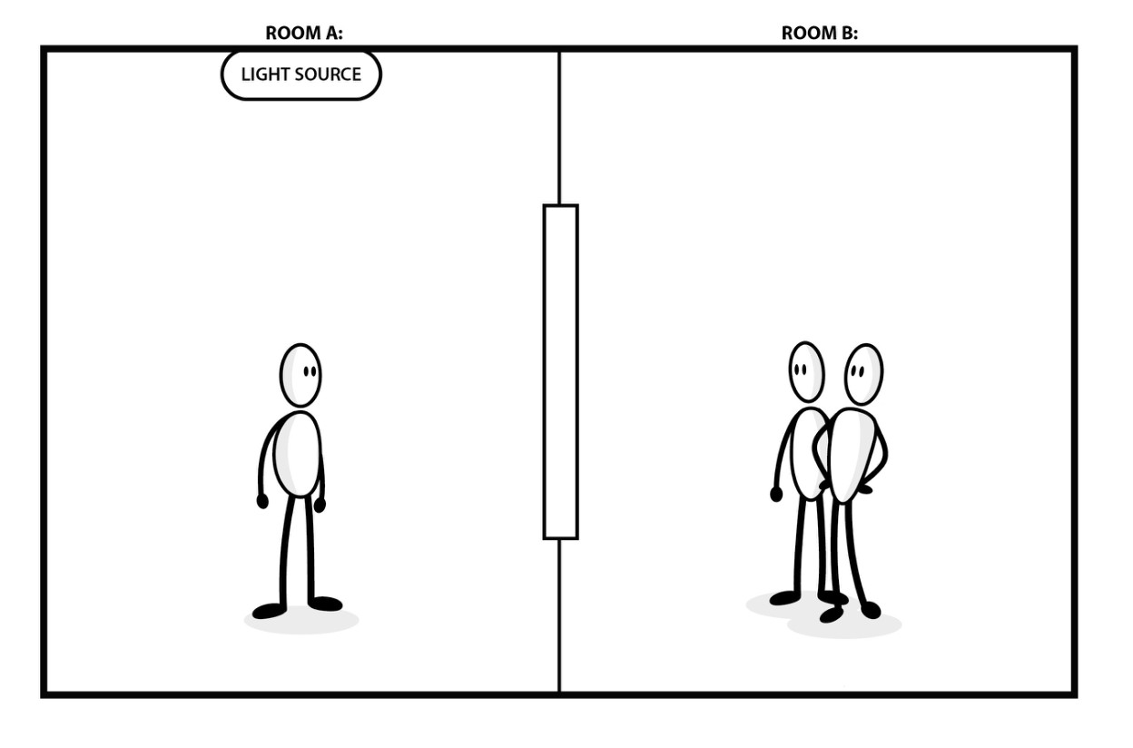
A ray 30° from the surface is 60° from the normal. Draw the local normal before labeling an angle.
Pause and explain
Why must the reference line be explicit?
Check your reasoning after answering
The reflection and refraction equations use angles relative to the normal; a surface-angle convention must first be converted.
Part 2 · Use Snell’s law and its conditions
The refractive index n=c/v describes phase speed relative to vacuum. Snell’s law n₁sinθ₁=n₂sinθ₂ applies to the stated interface model. Entering higher n bends a ray toward the normal except at normal incidence. Total internal reflection can occur when traveling from higher to lower n and the required sine would exceed one; the critical angle satisfies sinθc=n₂/n₁. It does not occur for every ray entering glass from air.
Read the visual model
Identify the labeled structures and units, then trace the arrows or compare values under the caption’s stated conditions. Separate the displayed evidence from a further inference. Write your reasoning before opening the guidance.
For n₁=1.5 and n₂=1.0, estimate the critical angle.
Visual reasoning — after your attempt
θc=arcsin(1/1.5)≈41.8° from the normal.
For suitable media, n₁ sinθ₁=n₂ sinθ₂ relates ray directions at an interface. A ray entering a larger refractive index bends toward the normal in the ordinary model. Total internal reflection requires travel from larger to smaller index and an incidence angle exceeding the critical value.
A ray from air into glass does not meet the larger-to-smaller condition for total internal reflection, even at a large incident angle.
Pause and explain
What two conditions are needed for total internal reflection?
Check your reasoning after answering
The initial medium must have larger refractive index, and the incidence angle measured from the normal must exceed the critical angle.
Part 3 · Use a consistent thin-lens convention
In the stated thin-lens convention, 1/f=1/do+1/di, with f positive for a converging lens, do positive for a real object and di positive for a real image on the far side. Magnification m=−di/do gives image height divided by object height. For f=10 cm and do=20 cm, di=20 cm and m=−1: the real image is inverted and equal in height. State the convention rather than interpreting every negative sign as an error.
Read the visual model
Identify the labeled structures and units, then trace the arrows or compare values under the caption’s stated conditions. Separate the displayed evidence from a further inference. Write your reasoning before opening the guidance.
What happens for this lens with a real object at do=5 cm?
Visual reasoning — after your attempt
di=−10 cm and m=+2: an upright enlarged virtual image on the object side.
For a thin lens in the usual real-object convention, 1/f=1/do+1/di. A converging lens has positive f; a positive di denotes a real image on the opposite side. Magnification m=−di/do includes orientation. Name the convention because other texts can define signs differently.
A negative di in this convention denotes a virtual image on the object side. A real image can be projected onto an appropriately placed screen in the model.
Pause and explain
Does a negative image distance mean there is no image?
Check your reasoning after answering
No. It identifies a virtual image under the selected convention; the ray extensions rather than outgoing rays meet at that location.
Part 4 · Check ray geometry against the numerical image
A ray diagram predicts an image by tracing directions from the same object point. In this thin-lens 2f case, a ray parallel to the axis leaves through the far focus, while the ray through the optical center is approximately undeviated. Their actual intersection gives the inverted real image at 2f. For a virtual image, backward extensions intersect instead; the actual outgoing rays do not meet there. A diagram and equation should agree on side, orientation and relative size.
Read the visual model
Identify the labeled structures and units, then trace the arrows or compare values under the caption’s stated conditions. Separate the displayed evidence from a further inference. Write your reasoning before opening the guidance.
Why is this image real rather than virtual?
Visual reasoning — after your attempt
The transmitted rays actually converge at the image point on the far side of the lens.
A ray sketch should match whether the image is real or virtual, enlarged or reduced, and upright or inverted. Thin-lens equations are approximations for suitable paraxial rays and idealized optics. Aberrations, lens thickness, and alignment can change actual image quality.
An object outside a converging lens’s focal distance commonly gives a real inverted image; inside it gives a virtual upright image in this model.
Pause and explain
Why should a correct equation result still be checked with a ray sketch?
Check your reasoning after answering
The sketch exposes sign or orientation errors and makes the model assumptions and image meaning easier to assess.
Apply the whole unit · Predict and test a lens image
Illustrative converging thin lens has f=+10.0 cm; a real object is 30.0 cm in front. Use positive do for a real object and positive di for a real image opposite it.
Your task
Calculate image distance and magnification, describe screen placement and orientation, then predict the qualitative change if the object moves inside the focal distance.
What your response should show
- Define the system, quantities, units, and relevant conditions before selecting a model.
- Show intermediate calculations or a labeled evidence account, including signs or denominators.
- Explain how the supplied evidence supports the conclusion rather than reporting only an answer.
- Identify a meaningful uncertainty, model limit, or measurement needed to test the conclusion.
Response guidance — after your attempt
1/di=1/10.0−1/30.0=1/15.0 cm⁻¹; di=+15.0 cm.
m=−15.0/30.0=−0.500: inverted image with half the object height.
Place a screen about 15.0 cm on the opposite side; inside f, the ideal image becomes virtual and upright.
The sign and scale agree with a converging-lens ray model for an object beyond twice the focal length. A screen tests a real image prediction, but image sharpness also depends on alignment and optical limitations. A virtual image cannot be captured by placing a screen at its apparent location in this simple setup.
Scientific references and source-model foundations
- OpenStax — thin-lens image formation
- OpenSciEd 8.2 — sound-wave foundations
- OpenSciEd public middle-school figure license — CC BY 4.0
Parent / teacher teaching notes
Use a ray sketch and stated signs before equations. Do not use direct Sun imaging as a lens activity; supplied diagrams are sufficient for the prediction. Ask the learner to explain each symbol, axis, unit and arrow before calculating. Calculated examples, supplied illustrative records and actual historical observations are labeled separately. Selected public OpenSciEd middle-school source figures are foundation examples, not complete high-school editions or an endorsement; all advanced explanations are supplied locally.
The key idea
Light reflects at equal angles from the normal and refracts (bends) when its speed changes between media (n = c/v, Snell's law); lenses and mirrors form real or virtual images predicted by 1/f = 1/dₒ + 1/dᵢ.
Law of Reflection
θᵢ = θᵣ
θᵢ is the angle of incidence and θᵣ is the angle of reflection, both measured from the normal (the perpendicular to the surface).
Index of Refraction
n = c ÷ v
n is the index of refraction (no units); c is the speed of light in vacuum; v is the speed of light in the medium. n is always ≥ 1, and larger n means light slows more and bends more.
Snell's Law
n₁ sin θ₁ = n₂ sin θ₂
n₁ and n₂ are the indices of refraction of the two media; θ₁ and θ₂ are the angles from the normal in each medium. At the critical angle for total internal reflection, sin θc = n₂ ÷ n₁.
Thin-Lens / Mirror Equation
1 ÷ f = 1 ÷ dₒ + 1 ÷ dᵢ
f is the focal length; dₒ is the object distance; dᵢ is the image distance (negative for a virtual image). Magnification m = − dᵢ ÷ dₒ, where a negative m means an inverted image.
Worked examples
Example 1
- Use the index of refraction equation n = c ÷ v.
- n = (3 × 10⁸) ÷ (1.25 × 10⁸).
- = 2.4.
Example 2 · Worked application
- Use 1/f=1/d_o+1/d_i with positive real-object convention.
- 1/d_i=1/10−1/30=1/15.
- d_i=15 cm, positive for a real image in this convention.
State the sign convention; a negative image distance has a different interpretation.
Example 3
- Use the thin-lens equation 1 ÷ f = 1 ÷ dₒ + 1 ÷ dᵢ, so 1 ÷ dᵢ = 1 ÷ f − 1 ÷ dₒ.
- 1 ÷ dᵢ = 1 ÷ 10 − 1 ÷ 30 = 3 ÷ 30 − 1 ÷ 30 = 2 ÷ 30 = 1 ÷ 15.
- dᵢ = 15.
Example 4 · Find and fix the mistake
- Test the claim against the stated conditions: State the sign convention; a negative image distance has a different interpretation.
- Objects inside the focal length produce a virtual image in the thin-lens model.
State the sign convention; a negative image distance has a different interpretation.
Example 5 · Reason from the visual model
- In the stated thin-lens convention, 1/f=1/do+1/di, with f positive for a converging lens, do positive for a real object and di positive for a real image on the far side. Magnification m=−di/do gives image height divided by object height. For f=10 cm and do=20 cm, di=20 cm and m=−1: the real image is inverted and equal in height. State the convention rather than interpreting every negative sign as an error.
- di=−10 cm and m=+2: an upright enlarged virtual image on the object side.
Calculated thin-lens cases; paraxial rays and negligible lens thickness are assumed.
Avoid these mistakes
- Optically denser means higher refractive index, not necessarily greater mass density.
Check your understanding
Light enters a higher-index medium obliquely. Explain direction.
Discuss the answer
It slows in the simple model and bends toward the normal. Frequency stays continuous across a stationary boundary; wavelength changes.
Return to the phenomenon
Return to the initial case. Why does a lens form an inverted image in one position and an upright one in another? Revise your drawing or explanation using two named ideas and one stated limitation.
Compare explanations after your attempt
Lens equations and ray intersections change the image side and orientation; inside f the image is virtual and upright.
What should we investigate next?
Which comparison would test a remaining uncertainty? State what you would change, keep comparable and measure.
Investigate, calculate and revise
Keep a first model and an evidence-supported revision. Attempt each task before opening guidance; all required explanations and supplied-data routes are available locally.
Activity 1 · Return to the opening case
Use the opening phenomenon, unit definitions and explained Parts 1–4.
Your task
Return to the initial case. Why does a lens form an inverted image in one position and an upright one in another? Revise your drawing or explanation using two named ideas and one stated limitation.
Success criteria
- Use the stated observations and appropriate units.
- Connect a labeled model with the physical/environmental mechanism.
- State assumptions and an evidence limitation.
- Explain a substantive revision or next test.
Hint
Keep object/material identity, material transfer and energy account distinct.
Response guidance — discuss after your attempt
Lens equations and ray intersections change the image side and orientation; inside f the image is virtual and upright.
Activity 2 · Transfer to a changed case
Cover the worked answer and use the explained models, relationships and notebook.
Your task
A thin converging lens has f=12 cm and a real object at 36 cm. Find image distance and magnification; describe the image.
Success criteria
- Use the stated measurements or conditions, with correct units.
- Connect the result to the physical or environmental mechanism or evidence relationship.
- Identify the assumption, model limit or further evidence requested.
Hint
Name known quantities and conditions, show intermediate steps and check conservation.
Response guidance — discuss after your attempt
1/di=1/12−1/36=1/18, so di=18 cm and m=−18/36=−0.50. It is real, inverted and half the object height in this paraxial model.
Words to know
- reflection
- The bouncing of light off a surface; the angle of incidence equals the angle of reflection, both measured from the normal.
- normal
- The imaginary line drawn perpendicular to a surface at the point where a ray strikes it; all angles are measured from it.
- refraction
- The bending of light as it changes speed passing from one medium into another.
- index of refraction (n)
- How much a medium slows light: n = c ÷ v, where v is light's speed in the medium; larger n means slower light and more bending.
- total internal reflection
- When light in a higher-index medium strikes a boundary beyond the critical angle and is entirely reflected back, as in a fiber-optic cable.
- focal length (f)
- The distance from a lens or mirror to the point where parallel rays converge (or appear to diverge from).
- real vs. virtual image
- A real image forms where light rays actually converge and can be projected on a screen; a virtual image only appears to come from where rays seem to originate.
Mirages, twinkling stars, and the atmosphere as a lens
Refraction does not need a block of glass — air of different temperatures has slightly different densities, and therefore different indices of refraction, so light bends as it passes through. A hot road heats the air just above it, bending light from the sky upward into your eyes and painting a shimmering 'puddle' — a mirage. The same continuous bending makes stars twinkle as their light threads through turbulent air, lets us see the Sun for a couple of minutes after it has geometrically set, and is why astronomers prize mountaintop and space telescopes above the wobbling atmosphere.
Total internal reflection: how light carries the internet
Beyond the critical angle, light striking the boundary of a higher-index medium is reflected entirely back inside — total internal reflection, an all-or-nothing effect. A fiber-optic cable is a hair-thin glass thread engineered so that light pulses always strike its walls beyond that angle, bouncing thousands of times and staying trapped as they race across continents and under oceans, carrying nearly all the world's internet and phone traffic. The same effect makes a cut diamond sparkle, repeatedly trapping and re-releasing light among its facets, and lets a doctor's endoscope pipe an image out of the body.
Your eye is a lens — and glasses move the image onto the retina
The human eye focuses a real, inverted image onto the retina, using a flexible lens that changes shape to focus near and far. When the eyeball is a touch too long, the image lands in front of the retina and distant objects blur — nearsightedness, corrected by a diverging lens that pushes the focus back. Too short an eyeball does the opposite — farsightedness, corrected by a converging lens. Eyeglasses, contacts, and laser surgery are all just applications of the thin-lens equation, nudging the image onto the retina where it belongs.
Real vs. virtual images: the idea that trips everyone up
The single most confusing point in optics is the difference between the two kinds of image. A real image forms where light rays actually cross, so you can catch it on a screen — the image on a camera sensor, a projector screen, or your retina, and it is inverted. A virtual image forms where rays only appear to originate but never truly meet, so it cannot be projected — your upright reflection in a bathroom mirror, or the enlarged view through a magnifying glass. In the thin-lens equation, a negative image distance is the mathematical signal that the image is virtual.
From Alhazen to the telescope: a short history of light's path
Around 1020, the Arab scholar Ibn al-Haytham (Alhazen) overturned the ancient idea that vision worked by beams shooting out of the eye, arguing instead that light reflects from objects into the eye — and he studied lenses, mirrors, and refraction with careful experiments, earning the title 'father of optics.' Centuries later, spectacle-makers' lenses were combined into the first telescopes; Galileo turned one skyward in 1609 and saw Jupiter's moons, and Newton built a reflecting telescope using a curved mirror instead of a lens. Every modern camera, microscope, and observatory descends from this long refinement of a few simple rules about how light bends and bounces.
In the real world
Every fiber-optic cable carrying internet traffic relies on total internal reflection, trapping pulses of light so they bounce along the glass thread for kilometers without escaping.
Exit check
Light enters a higher-index medium obliquely. Explain direction.
Check your explanation after answering
It slows in the simple model and bends toward the normal. Frequency stays continuous across a stationary boundary; wavelength changes.
Explain your reasoning without notes. If a key idea is missing, revisit the lesson and try again.
Superposition, Standing Waves & Resonance
Learning goals
- I can combine wave displacements and identify nodes and antinodes.
- I can calculate fixed-string harmonics and explain resonance limits.
Readings for this unit
Before this unit
Wave frequency, wavelength, speed, and signed displacement.
Use the detailed parent plan: two core 50–60-minute sessions per focused unit, with a third assigned for selected calculation/modeling topics. First study the core explanation and Parts 1–2 with their figures/checks; next study Parts 3–4, the whole-unit application, worked cases, varied practice and exit check. Attempt reasoning before opening guidance. Extend time when actual understanding requires it; investigations and chapter assessments have separate sessions.
Start with something to explain
Why can the same rope support only certain standing patterns?
Illustrative evidence case. Both ends are fixed and different driving frequencies produce nodes at specific positions.
Notice and wonder
Record two observations using the stated quantities or relationships. Keep observations separate from possible causes. Write one question that a new measurement could help answer.
Why can the same rope support only certain standing patterns?
Your first model
Label nodes, antinodes and the length boundary.
Build the language from the idea
- node
- A position of zero displacement in an ideal standing wave.
- antinode
- A position with maximal oscillation amplitude.
- resonance
- Large driven response near a system’s natural frequency.
The superposition principle states that overlapping small-amplitude linear waves add their displacements at each position and time. Two positive crests can reinforce, while a crest and matching trough can cancel momentarily. After passing, ideal waves continue; cancellation does not mean the wave energy has permanently vanished.
Constructive interference occurs where wave phases align; destructive interference where they oppose. Path difference mλ gives constructive interference for coherent in-phase sources, and (m+½)λ gives destructive interference in the simplest equal-source model. Source phase and geometry must be specified.
Oppositely traveling waves of the same frequency can form a standing pattern. Nodes have zero displacement and antinodes maximum oscillation in the ideal model. Adjacent nodes are λ/2 apart. The pattern does not travel down the string even though it arises from traveling-wave components.
For a string fixed at both ends, allowed standing wavelengths are λn=2L/n and frequencies fn=nv/(2L), n=1,2,3…. The fundamental is n=1. An air column’s allowed modes depend on whether each end is open or closed; do not apply the fixed-string formula to all instruments.
Resonance occurs when a drive near a system’s natural frequency transfers energy efficiently over cycles. Damping limits amplitude and broadens the response. Resonance can be useful in instruments and sensors or problematic in structures; the actual response depends on coupling, damping, and forcing amplitude.
Use a soft rope or audio examples at comfortable volume. A measured standing-wave pattern can test the wavelength relation, but the ideal linear model fails for large stretches or complicated boundaries. Identify mode number, length, and boundary conditions before calculating speed.
Build your understanding
Use the detailed parent plan: two core 50–60-minute sessions per focused unit, with a third assigned for selected calculation/modeling topics. First study the core explanation and Parts 1–2 with their figures/checks; next study Parts 3–4, the whole-unit application, worked cases, varied practice and exit check. Attempt reasoning before opening guidance. Extend time when actual understanding requires it; investigations and chapter assessments have separate sessions.
Part 1 · Apply superposition within a linear model
Superposition in a linear model means total displacement is the algebraic sum of contributions at the same location and instant. Two in-phase equal-amplitude waves can produce 2A locally; two opposite-phase contributions can cancel displacement at a point. Cancellation does not mean energy has been universally destroyed: the full wave and boundary account determines its redistribution. Separate diagrams on stacked rows are a comparison device, not three simultaneously separate ropes.
Read the visual model
Identify the labeled structures and units, then trace the arrows or compare values under the caption’s stated conditions. Separate the displayed evidence from a further inference. Write your reasoning before opening the guidance.
What total displacement results from+3 mm and−2 mm contributions?
Visual reasoning — after your attempt
+1 mm at that same point and instant under the linear model.
When compatible small disturbances overlap, a linear model adds signed displacements at each point. Constructive and destructive interference depend on phase. Destructive interference at one location does not mean energy is universally destroyed; the full pattern and energy account must be considered.
Two equal opposite displacements can sum to zero momentarily at a point while the waves continue to propagate elsewhere.
Pause and explain
Does a zero local displacement prove no waves are present?
Check your reasoning after answering
No. Opposing contributions can cancel locally; observations at other points or times can reveal the individual waves.
Part 2 · Connect path difference and phase
Phase specifies where an oscillation lies within its cycle. For coherent, initially in-phase sources in the same medium, a path difference of one wavelength adds a full cycle and restores phase agreement; half a wavelength produces opposition. Coherence means a stable phase relationship over the relevant interval. Source phase, reflections and unequal amplitudes can alter the simple bright/dark or loud/quiet pattern, so state those conditions before using path-difference rules.
Read the visual model
Identify the labeled structures and units, then trace the arrows or compare values under the caption’s stated conditions. Separate the displayed evidence from a further inference. Write your reasoning before opening the guidance.
Does half-wavelength path difference always guarantee complete cancellation?
Visual reasoning — after your attempt
No. It also needs the appropriate source phase, matched contributions and the linear coherent model.
For coherent waves of the same frequency with the same initial phase, integer-wavelength path differences give constructive interference; odd half-wavelength differences give destructive interference. Source phase differences can modify those conditions. State coherence and initial phase rather than using the path rule universally.
A half-wavelength longer path introduces a half-cycle phase difference in this same-phase-source model.
Pause and explain
Why is path difference alone sometimes insufficient?
Check your reasoning after answering
The sources may already have a phase difference or lack stable coherence, changing or washing out the predicted pattern.
Part 3 · Use standing-wave boundary conditions
A standing wave has nodes of zero displacement amplitude and antinodes of maximum amplitude, produced by counterpropagating coherent waves under appropriate conditions. A string fixed at both ends has nodes there and supports L=nλ/2. The displayed second harmonic has an additional middle node. Air columns with an open end have different displacement/pressure boundary conditions; do not transfer the fixed-string formula without identifying what is constrained.
Read the visual model
Identify the labeled structures and units, then trace the arrows or compare values under the caption’s stated conditions. Separate the displayed evidence from a further inference. Write your reasoning before opening the guidance.
For L=1.2 m in the shown second harmonic, what is λ?
Visual reasoning — after your attempt
L=2λ/2, so λ=1.2 m.
Standing waves arise from suitable overlapping waves traveling in opposite directions. Nodes have zero displacement amplitude; antinodes have maximum amplitude. Allowed patterns depend on boundaries. A string fixed at both ends has node endpoints and wavelengths λn=2 L/n in the ideal model.
A pipe open at both ends and a pipe closed at one end have different boundary conditions; do not copy the fixed-string pattern into every resonator.
Pause and explain
Why do boundary conditions determine allowed wavelengths?
Check your reasoning after answering
The pattern must fit the required nodes or antinodes at the ends, restricting which spatial arrangements persist.
Part 4 · Explain resonance and damping together
Resonance is an enhanced response when periodic driving couples effectively to a system’s natural oscillation. Damping removes mechanical energy and limits the steady response; the peak depends on the damping and on which response is measured. The plotted calculated displacement response is finite, rather than an unlimited growth claim. A real structure can have multiple modes and nonlinear behavior, so one simple resonance curve is a model to test.
Read the visual model
Identify the labeled structures and units, then trace the arrows or compare values under the caption’s stated conditions. Separate the displayed evidence from a further inference. Write your reasoning before opening the guidance.
Why does a resonance peak not justify saying the amplitude grows without limit?
Visual reasoning — after your attempt
Damping and other limits can balance input energy; the displayed model explicitly has a finite steady response.
Resonance involves a strong response near a system’s natural frequency under suitable driving. Damping and coupling determine response amplitude and width, so resonance is not unlimited growth in every real system. Compare response across driving frequencies while keeping other conditions controlled.
A broader response peak can reflect damping or other system behavior. One large oscillation alone does not identify the full resonance curve.
Pause and explain
What evidence supports a resonance-frequency claim?
Check your reasoning after answering
A controlled frequency sweep with measured response and repeated trials can locate a peak and characterize its width.
Apply the whole unit · Fit harmonics on a fixed string
Illustrative string length 0.800 m has wave speed 160 m/s and both ends fixed. Assume the ideal small-amplitude model.
Your task
Find the first three harmonic frequencies and wavelengths, describe nodes and antinodes, and explain why a differently constrained resonator needs a new pattern.
What your response should show
- Define the system, quantities, units, and relevant conditions before selecting a model.
- Show intermediate calculations or a labeled evidence account, including signs or denominators.
- Explain how the supplied evidence supports the conclusion rather than reporting only an answer.
- Identify a meaningful uncertainty, model limit, or measurement needed to test the conclusion.
Response guidance — after your attempt
Fundamental λ₁=2 L=1.60 m; f₁=160/1.60=100 Hz.
For n=2: λ₂=0.800 m and f₂=200 Hz.
For n=3: λ₃≈0.533 m and f₃=300 Hz.
The nth pattern has n half-wavelengths within the string, with nodes at both ends. The ideal frequency multiples depend on unchanged wave speed and fixed endpoints. Damping affects response, and a one-end-open acoustic resonator has different boundary conditions, so its allowed sequence cannot be inferred by copying these numbers.
Scientific references and source-model foundations
Parent / teacher teaching notes
Have students draw the first three spatial patterns and count half-wavelengths. Require a boundary statement rather than memorizing a frequency series. Ask the learner to explain each symbol, axis, unit and arrow before calculating. Calculated examples, supplied illustrative records and actual historical observations are labeled separately. Selected public OpenSciEd middle-school source figures are foundation examples, not complete high-school editions or an endorsement; all advanced explanations are supplied locally.
The key idea
Interference adds local displacement; boundary conditions select standing-wave modes.
Worked examples
Example 1
- f₁=v/(2L).
- 40/1.60.
Example 2 · Worked application
- The fundamental has half a wavelength over the string: λ₁=2L=2.4 m.
- f₁=v/λ₁=24/2.4=10 Hz.
- Both ends are displacement nodes.
Boundary conditions determine allowed wavelengths.
Example 3
- Add signed displacement at the same place/time.
- 3+(−2).
Example 4 · Find and fix the mistake
- Test the claim against the stated conditions: Boundary conditions determine allowed wavelengths.
- The pattern remains stationary while particles oscillate locally; nodes remain at zero displacement in the ideal mode.
Boundary conditions determine allowed wavelengths.
Example 5 · Reason from the visual model
- A standing wave has nodes of zero displacement amplitude and antinodes of maximum amplitude, produced by counterpropagating coherent waves under appropriate conditions. A string fixed at both ends has nodes there and supports L=nλ/2. The displayed second harmonic has an additional middle node. Air columns with an open end have different displacement/pressure boundary conditions; do not transfer the fixed-string formula without identifying what is constrained.
- L=2λ/2, so λ=1.2 m.
Original two opposite-phase snapshots of the same second-harmonic standing wave, not two traveling trajectories.
Avoid these mistakes
- A standing wave is a spatial pattern, not a wave moving with zero frequency.
Check your understanding
How could you estimate wavelength from a standing pattern?
Discuss the answer
Measure several adjacent node intervals, average, and double the node spacing.
Return to the phenomenon
Return to the initial case. Why can the same rope support only certain standing patterns? Revise your drawing or explanation using two named ideas and one stated limitation.
Compare explanations after your attempt
Counterpropagating contributions must satisfy endpoint constraints; damping and driving determine the response amplitude.
What should we investigate next?
Which comparison would test a remaining uncertainty? State what you would change, keep comparable and measure.
Investigate, calculate and revise
Keep a first model and an evidence-supported revision. Attempt each task before opening guidance; all required explanations and supplied-data routes are available locally.
Activity 1 · Return to the opening case
Use the opening phenomenon, unit definitions and explained Parts 1–4.
Your task
Return to the initial case. Why can the same rope support only certain standing patterns? Revise your drawing or explanation using two named ideas and one stated limitation.
Success criteria
- Use the stated observations and appropriate units.
- Connect a labeled model with the physical/environmental mechanism.
- State assumptions and an evidence limitation.
- Explain a substantive revision or next test.
Hint
Keep object/material identity, material transfer and energy account distinct.
Response guidance — discuss after your attempt
Counterpropagating contributions must satisfy endpoint constraints; damping and driving determine the response amplitude.
Activity 2 · Transfer to a changed case
Cover the worked answer and use the explained models, relationships and notebook.
Your task
A 1.5 m string fixed at both ends has wave speed 30 m/s. Find its fundamental and third-harmonic frequencies and the third-harmonic wavelength.
Success criteria
- Use the stated measurements or conditions, with correct units.
- Connect the result to the physical or environmental mechanism or evidence relationship.
- Identify the assumption, model limit or further evidence requested.
Hint
Name known quantities and conditions, show intermediate steps and check conservation.
Response guidance — discuss after your attempt
f1=v/(2L)=10 Hz; f3=30 Hz. λ3=2L/3=1.0 m, with fixed-end nodes in this ideal string model.
Words to know
- node
- A position of zero displacement in an ideal standing wave.
- antinode
- A position with maximal oscillation amplitude.
- resonance
- Large driven response near a system’s natural frequency.
In the real world
Use the chapter investigation to connect this unit to measured evidence and a practical decision.
Exit check
How could you estimate wavelength from a standing pattern?
Check your explanation after answering
Measure several adjacent node intervals, average, and double the node spacing.
Explain your reasoning without notes. If a key idea is missing, revisit the lesson and try again.
Doppler Effect & Relative Motion
Learning goals
- I can predict sound pitch changes with specified source/observer motion.
- I can choose a sound formula and distinguish it from electromagnetic shift models.
Readings for this unit
Before this unit
Wave frequency, speed, and fractions.
Use the detailed parent plan: two core 50–60-minute sessions per focused unit, with a third assigned for selected calculation/modeling topics. First study the core explanation and Parts 1–2 with their figures/checks; next study Parts 3–4, the whole-unit application, worked cases, varied practice and exit check. Attempt reasoning before opening guidance. Extend time when actual understanding requires it; investigations and chapter assessments have separate sessions.
Start with something to explain
Why does an approaching siren sound different without changing its own note?
Illustrative evidence case. Successive emitted fronts are closer together ahead of a moving source.
Notice and wonder
Record two observations using the stated quantities or relationships. Keep observations separate from possible causes. Write one question that a new measurement could help answer.
Why does an approaching siren sound different without changing its own note?
Your first model
Draw equal-time emission fronts and a fixed observer.
Build the language from the idea
- Doppler shift
- Change in observed frequency associated with relative motion.
- redshift
- An increase in observed wavelength relative to a reference.
Frequency observed from a moving wave source can differ from the emitted frequency. For sound, motion through the medium changes spacing between wavefronts, and observer motion changes their encounter rate. Approaching usually raises observed pitch and receding lowers it.
For a stationary observer and approaching source moving at vs below sound speed v, fobs=fsource v/(v−vs). For a receding source use v+vs in the denominator. These formulas assume a uniform stationary medium and a collinear geometry; source motion faster than sound requires a different treatment.
For observer motion and a stationary source, approaching gives fobs=fsource(v+vobserver)/v and receding gives (v−vobserver)/v. Both moving can be combined with careful signs. Sound speed is a property of the medium; it is not increased by the source’s motion.
Frequency and wavelength observed can change while the medium’s wave speed stays approximately fixed. With a moving source the emitted fronts are compressed ahead and spread behind. Pitch change is about frequency, while loudness changes depend additionally on distance, amplitude, and direction.
Electromagnetic Doppler shift is governed by relativistic relationships, not by sound’s stationary-medium formula. For low radial speeds relative to c, Δλ/λ≈vr/c is a useful approximation. A longer observed wavelength is redshift under this convention; the interpretation needs source and observer context.
Use diagrams or supplied acoustic measurements. Do not stand near traffic or moving machines to collect data. Distinguish the ideal constant-speed prediction from changing source angle, wind, reflection, or measurement uncertainty in actual sounds.
Build your understanding
Use the detailed parent plan: two core 50–60-minute sessions per focused unit, with a third assigned for selected calculation/modeling topics. First study the core explanation and Parts 1–2 with their figures/checks; next study Parts 3–4, the whole-unit application, worked cases, varied practice and exit check. Attempt reasoning before opening guidance. Extend time when actual understanding requires it; investigations and chapter assessments have separate sessions.
Part 1 · Distinguish source emission and received frequency
The Doppler effect is a difference between emitted and received frequency caused by relative motion in the stated wave model. For a sound source moving through still air, successive fronts are emitted from progressively shifted positions. Ahead of a subsonic source their spacing shrinks; behind it spacing grows. The source can keep the same vibration frequency while a stationary receiver encounters fronts at a different rate. Distinguish emitter clock rate from receiver arrivals.
Read the visual model
Identify the labeled structures and units, then trace the arrows or compare values under the caption’s stated conditions. Separate the displayed evidence from a further inference. Write your reasoning before opening the guidance.
Does the source need to vibrate faster for an approaching sound to have higher received frequency?
Visual reasoning — after your attempt
No. Source motion can compress front spacing even with an unchanged emission frequency.
Doppler shift concerns received frequency due to relative motion under a specified propagation model. The source can emit at a steady rate while a moving source or observer encounters altered wavefront intervals. The medium’s rest frame matters for ordinary sound.
A stationary microphone can receive a higher pitch from an approaching source even though the source oscillator has not changed its emission frequency.
Pause and explain
Does an approaching source necessarily emit at a higher frequency?
Check your reasoning after answering
No. The received wavefront timing changes; the source’s own emission rate can remain constant.
Part 2 · Use a diagram to choose signs
Sound formulas use velocities relative to the medium. A source approaching a fixed receiver shortens spacing to (v−vs)/f, so received frequency is fv/(v−vs). A moving receiver instead changes the speed at which it encounters existing fronts. Define positive approach speeds for this table rather than mixing signed coordinate velocities with an already signed formula. Draw the source, receiver, medium and propagation direction first.
Read the visual model
Identify the labeled structures and units, then trace the arrows or compare values under the caption’s stated conditions. Separate the displayed evidence from a further inference. Write your reasoning before opening the guidance.
For f=500 Hz,v=340 m/s and approaching vs=20 m/s, what is received f?
Visual reasoning — after your attempt
500×340/320=531.25 Hz in still air with a stationary receiver.
For one-dimensional sound, approaching motion generally raises received frequency and receding motion lowers it under the usual subsonic model. Choose signs by the actual motion and verify the limit of zero motion. Different formulas may define positive source and observer velocities differently.
A moving source compresses wavefront spacing ahead and stretches it behind. A moving observer changes the encounter rate through existing wavefronts.
Pause and explain
Why should a memorized plus sign not replace a diagram?
Check your reasoning after answering
Source and observer sign conventions differ across presentations; geometry and the approach-versus-recession check determine the correct case.
Part 3 · Keep sound and light models distinct
Light in vacuum does not use a stationary air-like medium. Its relativistic Doppler shift depends on the observer–source geometry and consistent inertial-frame definitions. For longitudinal recession, fobs=femit√[(1−β)/(1+β)] with β=v/c. This differs from simply replacing sound speed by c in the moving-source formula. The low-speed approximations can be similar, but their underlying assumptions and behavior at high speed differ.
Read the visual model
Identify the labeled structures and units, then trace the arrows or compare values under the caption’s stated conditions. Separate the displayed evidence from a further inference. Write your reasoning before opening the guidance.
For longitudinal recession at 0.60c, what fraction of emitted frequency is received?
Visual reasoning — after your attempt
√(0.40/1.60)=0.50; the observed frequency is half under the stated inertial model.
A sound formula can use source and observer speeds relative to a material medium. Light in vacuum has no ordinary sound-medium rest frame and requires a relativistic account when precision or speed demands it. Do not substitute c into an acoustic formula and call it universally valid for light.
At low speeds, some first-order approximations look similar, but their assumptions and full expressions differ.
Pause and explain
What must be specified before applying a Doppler formula?
Check your reasoning after answering
The wave type, propagation model, motion directions, and velocity reference frame must be specified.
Part 4 · Account for realistic observations
A received-frequency change does not identify a unique cause by itself. The source may change its emission rate; a moving medium can change sound propagation; source–receiver motion may have only a partial radial component. Reflections and multiple emitters can complicate the spectrum. Compare an emission reference, geometry and medium conditions before converting a shift into speed, and report the assumptions that make the calculation identifiable.
Read the visual model
Identify the labeled structures and units, then trace the arrows or compare values under the caption’s stated conditions. Separate the displayed evidence from a further inference. Write your reasoning before opening the guidance.
Why is the full speed of a passing source not always the speed to use in a one-dimensional formula?
Visual reasoning — after your attempt
Only the appropriate motion along the source–receiver direction enters that simplified geometry; the full trajectory needs a geometric model.
Wind, changing approach angle, source acceleration, reflections, and receiver processing can alter a recorded shift. A source passing a receiver may have a changing radial velocity component. An ideal straight-line calculation predicts a controlled case, not every observed sound sequence.
Measure the geometry and source emission frequency alongside the received signal if testing the model.
Pause and explain
Why may a passing-source shift vary continuously?
Check your reasoning after answering
The component of relative motion along the propagation direction changes with geometry, rather than remaining equal to the full source speed.
Apply the whole unit · Compare an approaching and receding sound source
Illustrative source emits 500 Hz and moves directly along a line at 20.0 m/s. A receiver is stationary in still air; sound speed is 340 m/s. Use the subsonic moving-source model.
Your task
Calculate received frequency while approaching and while receding, check the zero-speed limit, and explain why the two shifts are not exactly symmetric.
What your response should show
- Define the system, quantities, units, and relevant conditions before selecting a model.
- Show intermediate calculations or a labeled evidence account, including signs or denominators.
- Explain how the supplied evidence supports the conclusion rather than reporting only an answer.
- Identify a meaningful uncertainty, model limit, or measurement needed to test the conclusion.
Response guidance — after your attempt
Approach: f′=500×340/(340−20)=531.25 Hz.
Recession: f′=500×340/(340+20)≈472.22 Hz.
At zero source speed, both expressions return 500 Hz.
The altered wavefront spacing appears in the denominator, so equal positive and negative source speeds do not produce exactly equal frequency offsets. The model assumes direct-line motion, still air, and a stationary receiver; a passing source at an angle needs the relevant geometry rather than these two constant cases.
Scientific references and source-model foundations
Parent / teacher teaching notes
Ask learners to predict higher or lower frequency before arithmetic and test the stationary limit. Keep acoustic and relativistic formulas separate. Ask the learner to explain each symbol, axis, unit and arrow before calculating. Calculated examples, supplied illustrative records and actual historical observations are labeled separately. Selected public OpenSciEd middle-school source figures are foundation examples, not complete high-school editions or an endorsement; all advanced explanations are supplied locally.
The key idea
Relative motion changes observed frequency; use a formula appropriate to the wave and medium.
Worked examples
Example 1
- fobs=600×340/(340−20).
- 204000/320.
Example 2 · Worked application
- For an approaching subsonic source, f'=fv/(v−v_s).
- f'=500×340/(340−34)≈556 Hz.
- Approach compresses wavefront spacing in front of the source.
The formula changes for moving observers or other geometries.
Example 3
- fobs=600×340/(340+20).
- 204000/360.
Example 4 · Find and fix the mistake
- Test the claim against the stated conditions: The formula changes for moving observers or other geometries.
- The source can keep its emission frequency; motion changes the frequency received.
The formula changes for moving observers or other geometries.
Example 5 · Reason from the visual model
- Light in vacuum does not use a stationary air-like medium. Its relativistic Doppler shift depends on the observer–source geometry and consistent inertial-frame definitions. For longitudinal recession, fobs=femit√[(1−β)/(1+β)] with β=v/c. This differs from simply replacing sound speed by c in the moving-source formula. The low-speed approximations can be similar, but their underlying assumptions and behavior at high speed differ.
- √(0.40/1.60)=0.50; the observed frequency is half under the stated inertial model.
Original sound/light comparison; cosmological expansion requires an additional model beyond simple local recession.
Avoid these mistakes
- Use velocities relative to the medium for sound and check geometry.
Check your understanding
Why is observed pitch lower behind a receding sound source?
Discuss the answer
Wavefronts reaching the observer are spaced farther apart, reducing encounter frequency.
Return to the phenomenon
Return to the initial case. Why does an approaching siren sound different without changing its own note? Revise your drawing or explanation using two named ideas and one stated limitation.
Compare explanations after your attempt
Wave spacing and encounter rate change; sound uses medium-relative velocities while vacuum light needs relativistic treatment.
What should we investigate next?
Which comparison would test a remaining uncertainty? State what you would change, keep comparable and measure.
Investigate, calculate and revise
Keep a first model and an evidence-supported revision. Attempt each task before opening guidance; all required explanations and supplied-data routes are available locally.
Activity 1 · Return to the opening case
Use the opening phenomenon, unit definitions and explained Parts 1–4.
Your task
Return to the initial case. Why does an approaching siren sound different without changing its own note? Revise your drawing or explanation using two named ideas and one stated limitation.
Success criteria
- Use the stated observations and appropriate units.
- Connect a labeled model with the physical/environmental mechanism.
- State assumptions and an evidence limitation.
- Explain a substantive revision or next test.
Hint
Keep object/material identity, material transfer and energy account distinct.
Response guidance — discuss after your attempt
Wave spacing and encounter rate change; sound uses medium-relative velocities while vacuum light needs relativistic treatment.
Activity 2 · Transfer to a changed case
Cover the worked answer and use the explained models, relationships and notebook.
Your task
A 600 Hz source recedes at 30 m/s from a stationary observer in still air with sound speed 330 m/s. Find received frequency and compare with the approach case at the same speed.
Success criteria
- Use the stated measurements or conditions, with correct units.
- Connect the result to the physical or environmental mechanism or evidence relationship.
- Identify the assumption, model limit or further evidence requested.
Hint
Name known quantities and conditions, show intermediate steps and check conservation.
Response guidance — discuss after your attempt
Receding:600×330/360=550 Hz. Approaching:600×330/300=660 Hz. The shifts are not symmetric about 600 in this finite-speed source model.
Words to know
- Doppler shift
- Change in observed frequency associated with relative motion.
- redshift
- An increase in observed wavelength relative to a reference.
In the real world
Use the chapter investigation to connect this unit to measured evidence and a practical decision.
Exit check
Why is observed pitch lower behind a receding sound source?
Check your explanation after answering
Wavefronts reaching the observer are spaced farther apart, reducing encounter frequency.
Explain your reasoning without notes. If a key idea is missing, revisit the lesson and try again.
Problem 1
Answer and explanation
30 m/s
v = f × λ = 12 × 2.5 = 30 m/s.
Problem 2
Answer and explanation
100 Hz
f = 1 ÷ T = 1 ÷ 0.01 = 100 Hz.
Problem 3
Answer and explanation
4 Hz
f = v ÷ λ = 6 ÷ 1.5 = 4 Hz.
Problem 4
Answer and explanation
340 m
In 2 s the sound makes a round trip: total distance = 340 × 2 = 680 m. The cliff is half of that, since the sound goes there and back: 680 ÷ 2 = 340 m.
Problem 5
Answer and explanation
200 Hz
f = v ÷ λ = 340 ÷ 1.7 = 200 Hz.
Problem 6
Answer and explanation
Microwaves, infrared, ultraviolet, gamma rays
Energy increases as wavelength decreases along the spectrum. Of these four, the order from lowest to highest energy is microwaves → infrared → ultraviolet → gamma rays.
Problem 7
Answer and explanation
1 × 10¹⁵ Hz
f = c ÷ λ = (3 × 10⁸) ÷ (3 × 10⁻⁷) = 1 × 10¹⁵ Hz.
Problem 8
Answer and explanation
2 × 10⁸ m/s
Rearrange n = c ÷ v to v = c ÷ n = (3 × 10⁸) ÷ 1.5 = 2 × 10⁸ m/s.
Problem 9
Answer and explanation
−6 cm: an upright, magnified virtual image (as in a magnifying glass).
1 ÷ dᵢ = 1 ÷ f − 1 ÷ dₒ = 1 ÷ 12 − 1 ÷ 4 = 1 ÷ 12 − 3 ÷ 12 = −2 ÷ 12 = −1 ÷ 6, so dᵢ = −6 cm. The negative image distance means the image is virtual, upright, and enlarged — exactly how a magnifying glass works when the object is inside the focal length.
Problem 10
Answer and explanation
Louder — constructive interference.
When the two waves arrive in phase (crest-on-crest), superposition adds their amplitudes, producing a larger-amplitude — and therefore louder — sound. This reinforcement is called constructive interference.
Problem 11
Answer and explanation
680 Hz
The source approaches, so use the minus sign: f′ = f × v ÷ (v − vₛ) = 600 × 340 ÷ (340 − 40) = 600 × 340 ÷ 300 = 600 × 1.13333 = 680 Hz.
Problem 12
Answer and explanation
v=fλ=10 m/s andT=1/f=.20 s.
Response criteria
- State a scientifically accurate conclusion.
- Show the calculation or mechanism that supports it.
- Include units, conditions, or limits where relevant.
Problem 13
Answer and explanation
f=50 Hz and v=40 m/s. At100 Hz with the same40 m/s speed, λ=0.40 m.
f=50 Hz and v=40 m/s.
At100 Hz with the same40 m/s speed, λ=0.40 m.
Response criteria
- Use the stated measurements or conditions, with correct units.
- Connect the result to the physical or environmental mechanism or evidence relationship.
- Identify the assumption, model limit or further evidence requested.
Problem 14
Answer and explanation
Round-trip 170 m; one-way distance 85 m.
Response criteria
- State a scientifically accurate conclusion.
- Show the calculation or mechanism that supports it.
- Include units, conditions, or limits where relevant.
Problem 15
Answer and explanation
The intensity ratio is10^1.5≈31.6. Echo distance=340×0.30/2=51 m; the two calculations use different models and quantities.
The intensity ratio is10^1.5≈31.6.
Echo distance=340×0.30/2=51 m; the two calculations use different models and quantities.
Response criteria
- Use the stated measurements or conditions, with correct units.
- Connect the result to the physical or environmental mechanism or evidence relationship.
- Identify the assumption, model limit or further evidence requested.
Problem 16
Answer and explanation
f=c/λ=1×10⁸ Hz. Use meters with SI c.
Response criteria
- State a scientifically accurate conclusion.
- Show the calculation or mechanism that supports it.
- Include units, conditions, or limits where relevant.
Problem 17
Answer and explanation
λ=4.00×10⁻⁷ m; f=7.50×10¹⁴ Hz and E=4.97×10⁻¹⁹ J per photon. This is not total beam energy without photon number.
λ=4.00×10⁻⁷ m; f=7.50×10¹⁴ Hz and E=4.97×10⁻¹⁹ J per photon.
This is not total beam energy without photon number.
Response criteria
- Use the stated measurements or conditions, with correct units.
- Connect the result to the physical or environmental mechanism or evidence relationship.
- Identify the assumption, model limit or further evidence requested.
Problem 18
Answer and explanation
It slows in the simple model and bends toward the normal. Frequency stays continuous across a stationary boundary; wavelength changes.
Response criteria
- State a scientifically accurate conclusion.
- Show the calculation or mechanism that supports it.
- Include units, conditions, or limits where relevant.
Problem 19
Answer and explanation
1/di=1/12−1/36=1/18, so di=18 cm and m=−18/36=−0.50. It is real, inverted and half the object height in this paraxial model.
1/di=1/12−1/36=1/18, so di=18 cm and m=−18/36=−0.50.
It is real, inverted and half the object height in this paraxial model.
Response criteria
- Use the stated measurements or conditions, with correct units.
- Connect the result to the physical or environmental mechanism or evidence relationship.
- Identify the assumption, model limit or further evidence requested.
Problem 20
Hints
Write the relationship first; substitute with consistent units.
Answer and explanation
60 Hz
fn=nf 1=3×20.
Problem 21
Answer and explanation
Fixed, free, open, and closed boundaries allow different mode patterns.
Response criteria
- State a scientifically accurate conclusion.
- Show the calculation or mechanism that supports it.
- Include units, conditions, or limits where relevant.
Problem 22
Answer and explanation
f1=v/(2L)=10 Hz; f3=30 Hz. λ3=2L/3=1.0 m, with fixed-end nodes in this ideal string model.
f1=v/(2L)=10 Hz; f3=30 Hz. λ3=2L/3=1.0 m, with fixed-end nodes in this ideal string model.
Response criteria
- Use the stated measurements or conditions, with correct units.
- Connect the result to the physical or environmental mechanism or evidence relationship.
- Identify the assumption, model limit or further evidence requested.
Problem 23
Hints
Write the relationship first; substitute with consistent units.
Answer and explanation
377.78 Hz
400×340/360≈377.78.
Problem 24
Answer and explanation
No. Light requires electromagnetic relativistic Doppler relationships.
Response criteria
- State a scientifically accurate conclusion.
- Show the calculation or mechanism that supports it.
- Include units, conditions, or limits where relevant.
Problem 25
Answer and explanation
Receding:600×330/360=550 Hz. Approaching:600×330/300=660 Hz. The shifts are not symmetric about600 in this finite-speed source model.
Receding:600×330/360=550 Hz.
Approaching:600×330/300=660 Hz.
The shifts are not symmetric about600 in this finite-speed source model.
Response criteria
- Use the stated measurements or conditions, with correct units.
- Connect the result to the physical or environmental mechanism or evidence relationship.
- Identify the assumption, model limit or further evidence requested.